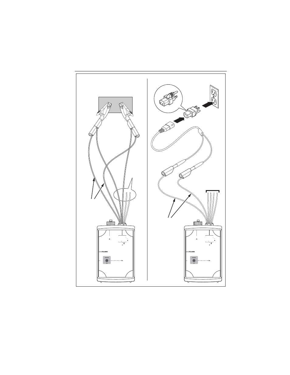
Power quality logger using the logger 13, Figure 3. supplying operating power to the logger, Voltage test leads – Fluke 1744 User Manual
Page 22: Power supply leads power supply leads
Power Quality Logger
Using
the
Logger
13
Voltage
Test Leads
POWER LOGGER
1743
START
STOP
POWER
2
3
2
S
R
I
N
I
3
I
2
I
1
V
3
V
2
V
1
CURRENT INPUT
10 V
RMS
MAX
L1/A
L2/B
L3/C
N
5 VA
45 -65 Hz
MEASUREMENT INPUT
SUPPLY INPUT
830 V
RMS
MAX CAT
600 V CAT
300 V CAT
100 -350 V
660 V MAX
88 -660 V
POWER LOGGER
1743
START
STOP
POWER
2
3
2
S
R
I
N
I
3
I
2
I
1
V
3
V
2
V
1
CURRENT INPUT
10 V
RMS
MAX
L1/A
L2/B
L3/C
N
5 VA
45 -65 Hz
MEASUREMENT INPUT
SUPPLY INPUT
830 V
RMS
MAX CAT
600 V CAT
300 V CAT
100 -350 V
660 V MAX
88 -660 V
Voltage
Test Leads
Power from Wall Outlet
Power in Parallel
with
Max 660 V
Test Leads
Power Supply
Leads
Power Supply
Leads
egb031.eps
Figure 3. Supplying Operating Power to the Logger
2. Connect the RS232 interface cable to the serial port of your PC.
This manual is related to the following products: