Connections for single-phase logging, Users manual, L1 n – Fluke 1744 User Manual
Page 29: L3 l2, Figure 6. single-phase logging
1744/1743
Users Manual
20
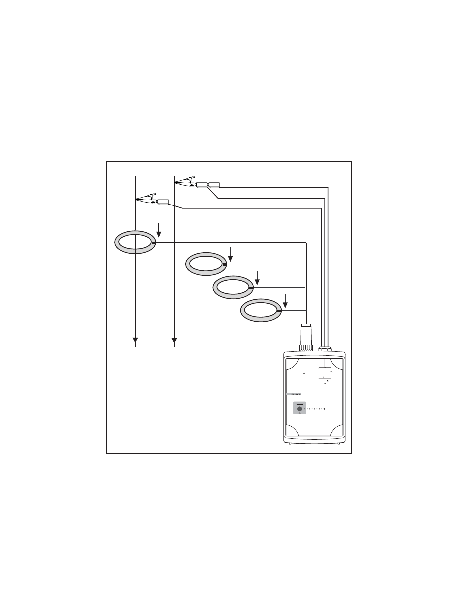
Connections for Single-Phase Logging
Figure 6 shows the connections for logging single-phase systems.
L1
N
POWER LOGGER
1743
START
STOP
POWER
2
3
2
S
R
I
N
I
3
I
2
I
1
V
3
V
2
V
1
CURRENT INPUT
10 V
RMS
MAX
L1/A
L2/B
L3/C
N
5 VA
45 -65 Hz
MEASUREMENT INPUT
SUPPLY INPUT
830 V
RMS
MAX CAT
600 V CAT
300 V CAT
100 -350 V
660 V MAX
88 -660 V
L3
L2
egb005.eps
Figure 6. Single-Phase Logging
This manual is related to the following products: