Tool settings, Switching the ma- chine on and off, Electronic control – Festool OF 2200 EB User Manual
Page 9: Chips extraction
9
Switching the ma-
chine on and off
Keep the machine steady
during switching and during use by hold-
ing the handles with both hands.
3.2
3.1
The switch [3.2] is an on/off switch. Press the
side locking knob [3.1] to lock the switch for
continuous operation. Press the switch again
to release the knob.
After the machine has been
switched off, the milling cutter will still
rotate for a time. Take care that parts of
your body do not come into contact with the
milling cutter while it is still rotating!
Tool settings
Always disconnect the plug
from the power supply before making
any adjustments to the router or install-
ing or removing any accessory!
Electronic control
The router OF 2200 EB has full-wave electron-
ics with the following functions:
Smooth start-up:
The electronically controlled smooth start-up
function ensures that the machine starts up
smoothly.
Speed regulation:
6
7
8
9
80
70
60
50
40
30
20
10
0
4.1
You can regulate the rotational speed step-
lessly between 10000 and 22000 rpm using
the adjusting wheel [4.1]. This enables you to
optimise the cutting speed to suit the respec-
tive material and routing tool:
Material
Cutter diameter [mm] Cutter
material
10-30 30-50 50-89
Hard
wood
6-4
5-3
3-1
HW
(HSS)
Soft wood
6-5
6-4
5-3
HSS
(HW)
Panels
6-5
6-4
4-2
HW
Plastic
6-4
6-3
3-1
HW
Alumini-
um
3-1
3-1
2-1
HSS
(HW)
Plaster-
board
2-1
1
1
HW
Constant speed:
The selected motor speed is electronically
maintained to a constant level. By this means
a uniform cutting speed is achieved.
Brake
The OF 2200 EB has an electronic brake,
which stops the spindle within a few seconds
of the machine switching off.
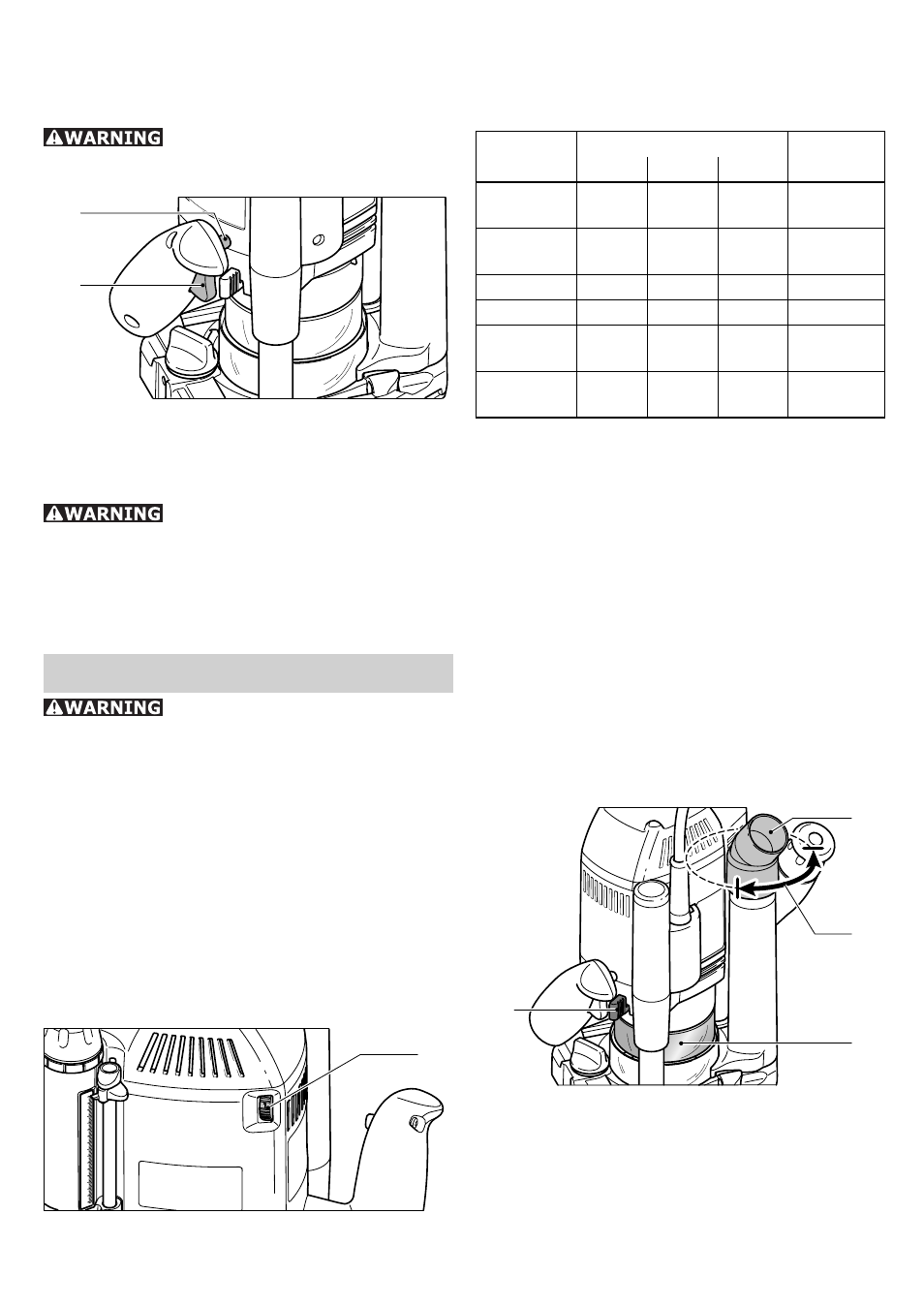
Chips extraction
A Festool dust extractor with an extractor
hose diameter of 36 mm or 27 mm (36 mm
recommended due to the reduced risk of
clogging) can be connected to the extractor
connector [5.4].
5.2
5.1
5.4
5.3
The extractor connector [5.4] can be rotated
within the range indicated [5.3]. The extractor
connector on the extraction pipe will no longer
be secure if rotated outside of this range.
Chip guard
The chip guard [5.2] can be moved to the
top position to change the router bit, for ex-