FUJITSU MCP3130SS User Manual
Page 64
Installation Requirements
3-22 C156-E228-02EN
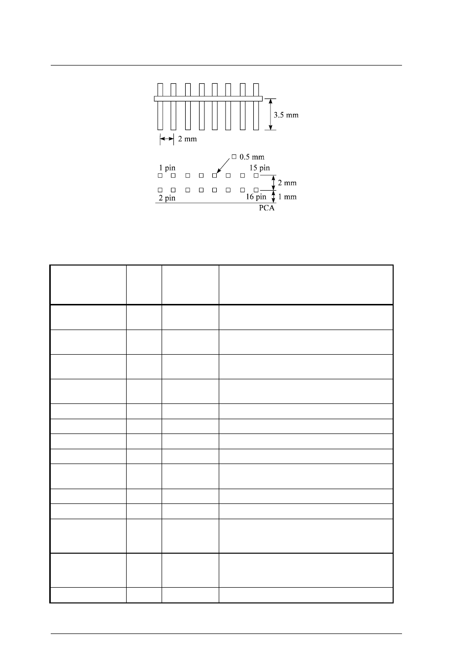
Figure 3.17
External operator panel interface connector
Table 3.4 External operator panel interface
Signal Pin
Reference
setting
signal
Function
SCSI-ID 4
2
SW1-01
Equivalent to ON position of SW1-01 by
shorting with 0 V.
SCSI-ID 2
4
SW1-02
Equivalent to ON position of SW1-02 by
shorting with 0 V.
SCSI-ID 1
6
SW1-03
Equivalent to ON position of SW1-03 by
shorting with 0 V.
Device type mode
9
SW1-06
Equivalent to ON position of SW1-06 by
shorting with 0 V. See 3.4.4 (1)
Not assigned
10
–
–
Verify mode
11
–
See 3.4.4 (3)
Not assigned
13
–
–
SCSI type-0
14
–
See 3.4.4 (5)
SCSI terminating
resistor mode
15
CNH1(5-6)
Equivalent to shorting CNH1 05-06 by shorting
with 0 V.
+LED
3
–
LED+terminal for external connection
–LED
5
–
LED–terminal for external connection
*EJSW
7
–
External eject instruction input (TTL-IC level)
L level: Equivalent to pushing eject switch
H level: Equivalent to not pushing eject switch
CTRGIN
1
–
External cartridge sensor output (TTL-IC level)
L level: No cartridge in drive
H level: Cartridge in drive
0 V (GND)
8, 12, 16
–
0 V