FUJITSU MCP3130SS User Manual
Page 29
1.2 Configuration of Optical Disk Drive
C156-E228-02EN 1-9
Driver circuit section
Read Amp
Power Amp
Filter
Sensor
Motor Driver
Bias Coil
Eject Motor
Cartridge Sensor
Actuator section
Focus Act.
Track Act.
Spindle Motor
Temperature Sensor
Mecha section
Head section
Laser Diode
Photo Diode
APC Amp
LPC Amp
Head Amp
F-ROM
D-RAM
SCSI I/F
SCSI controller circuit
section
MPU
ODC
DSP
User Logic
LSI i/f
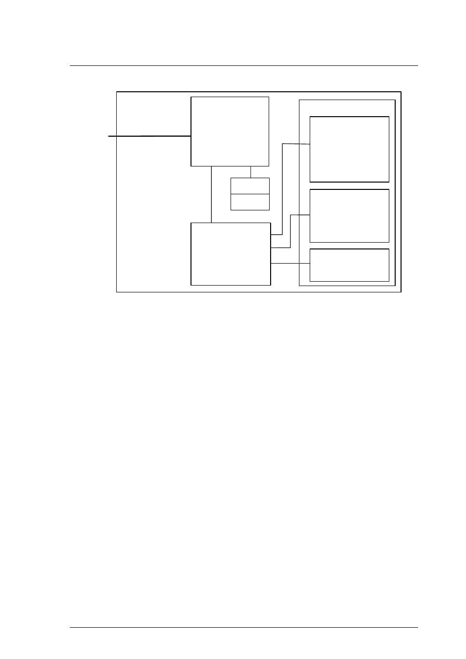
Figure 1.4 Block diagram of the control circuit section
The control circuit consists of a SCSI controller, which controls operations
between the SCSI interface and the drive interface, and a device circuit section,
which controls the drive circuit.
(1) SCSI controller circuit section
The SCSI controller circuit, which uses an LSI for improved reliability, controls
the drive through SCSI interface control, read-write control, beam control, etc., by
using one high-speed microprocessor (MPU).
(2) Drive circuit section
The drive circuit section consists of the laser diode light emitting control circuit,
signal reproduction circuit, servo/seek control circuit, rotation control circuit, and
other control circuits. In particular, the servo/seek control circuit consists of a
DSP (digital signal processor) for circuit reduction and the realization of a simple
configuration.
The drive circuit section performs the seek, erase, record, and playback operations
while controlling the focus tracking of the beam.