2 power supply for terminating resistor – FUJITSU MCP3130SS User Manual
Page 114
SCSI BUS
7-12 C156-E228-02EN
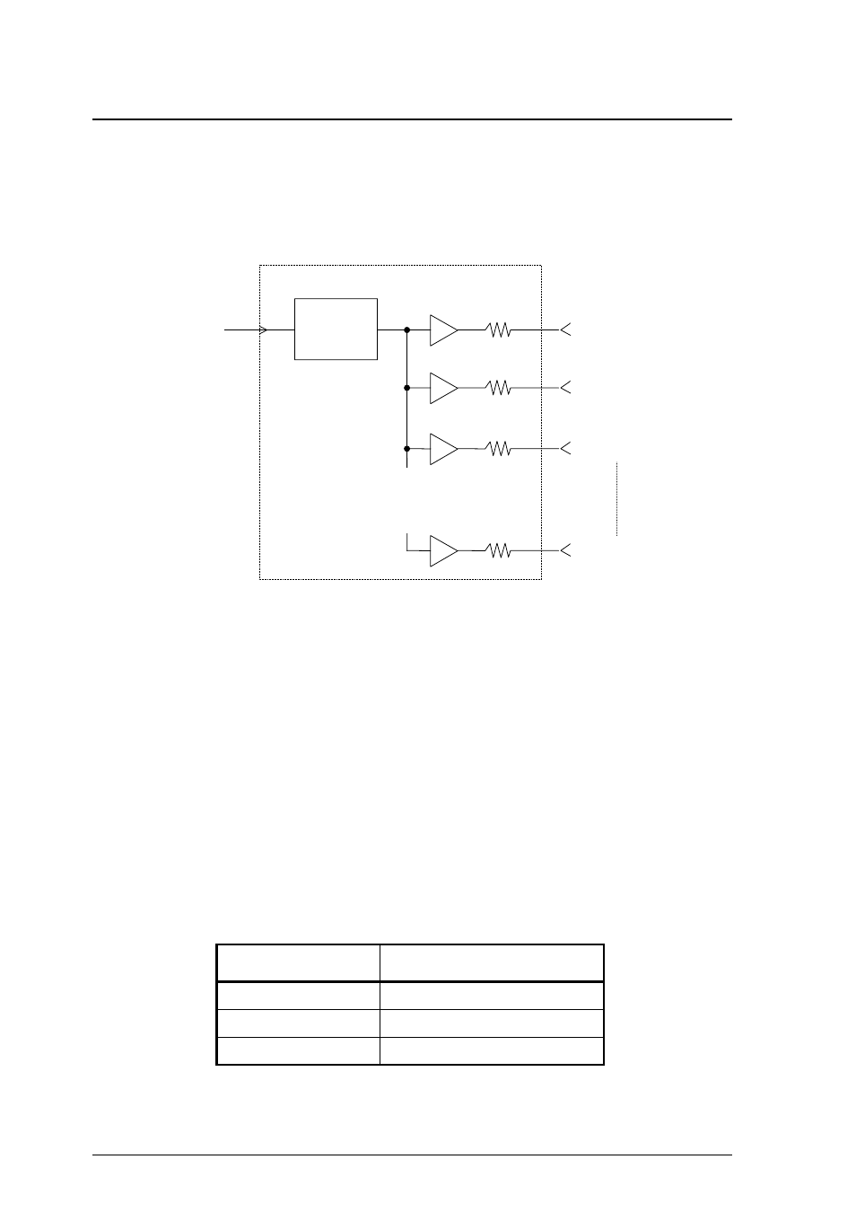
(2) Termination circuit
The termination circuit is a resistor termination as shown in Figure 7.8. The
termination circuits are installed in SCSI devices which are connected at both ends
of the interface cable.
TERMPWR
or +5 VDC
V
IN
2.6V
Generater
Resistor
110
Ω
, 0.5%
R
2
R
3
R
18
–SCSI LINE 18
–SCSI LINE 3
–SCSI LINE 2
–SCSI LINE 1
•
•
•
•
•
•
•
•
•
Figure 7.8 SCSI termination circuit
7.4.2 Power supply for terminating resistor
The TERMPWR signal on the interface connector is used to supply power to the
terminating resistor circuit connected to both ends of the cable. In a system
configuration where the terminating resistor is installed outside the SCSI device or
if there is a possibility of the power to the SCSI device with the terminating
resistor being cut off, power for the terminating resistor must be supplied to the
TERMPWR line from an SCSI device on the bus. The SCSI device always
working as an INIT (example: host adapter) should supply that power. Power
must be supplied to the TERMPWR line through a diode or other element to
prevent reverse current.
Table 7.3 lists the requirements for terminating the resistor power supply (V
term
)
Table 7.3 Requirements for terminating resistor power supply
Item Single-ended
type
Output voltage
4.25 to 5.25 VDC
Current capacity
900 mA min.
Sink current
1.0 mA max.