Configuration diagram primergy r450 – FUJITSU R450 User Manual
Page 3
System configurator and order-informtion guide
PRIMERGY R450 Status 2003-10-24
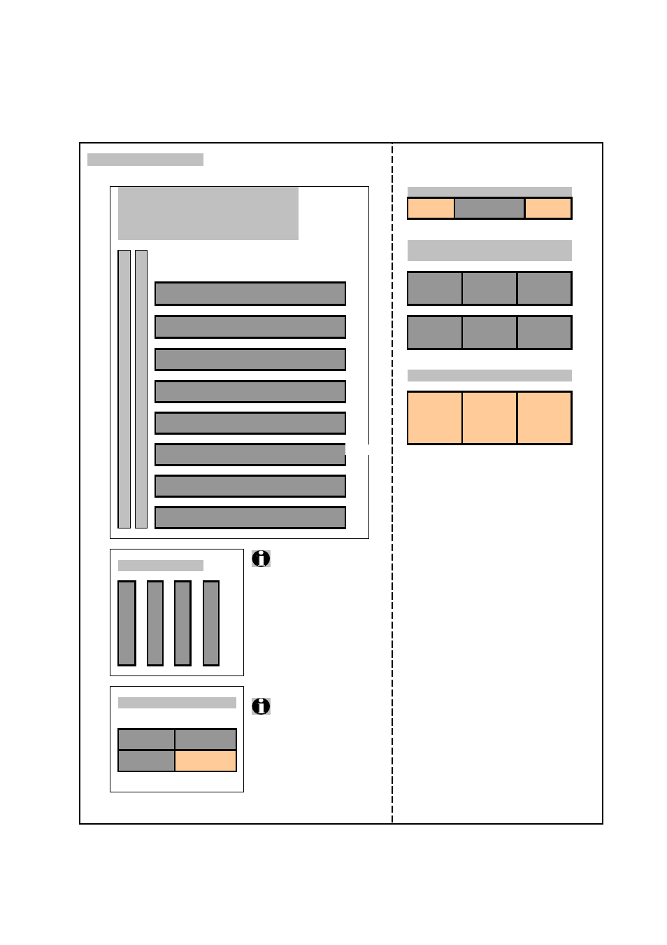
Configuration diagram PRIMERGY R450
TOP VIEW
FRONT VIEW
System unit ( I )
Extension slots
Peripheral Bay ( V )
Graphics ( IV )
3.5"x0.5"
LCD
SCSI controller ( VII )
floppy disk
Disk array ( VIII )
Communication/Network ( IX )
Hard Disk Drives ( VI )
2 channels
Channel 1
3.5"x1"
3.5"x1"
3.5"x1"
1
8
PCI-X long 64 Bit / 100 MHz hot-plug
SCSI-ID 0
SCSI-ID 1
SCSI-ID 2
Channel 0
1
7
PCI-X long 64 Bit / 100 MHz hot-plug
3.5"x1"
3.5"x1"
3.5"x1"
SCSI-ID 0
SCSI-ID 1
SCSI-ID 2
2
6
PCI long 64 Bit / 66 MHz hot-plug
Hot-plug power supply 500W ( I )
3
5
PCI-X long 64 Bit / 100 MHz hot-plug
3. PS
2. PS
1.PS
4
4
PCI-X long 64 Bit / 100 MHz hot-plug
Interface: WIDE SCA (80 pins)
5
3
PCI-X long 64 Bit / 100 MHz hot-plug
6
2
PCI long 32 Bit / 33 MHz
6
1
PCI long 32 Bit / 33 MHz
Memory ( III )
The highest assembled bank
is the hot-spare bank,
if the feature is enabled
Processor ( II )
Processors must be plugged
in order according the picture
Xeon MP 3
Xeon MP 4
Xeon MP 2
Xeon MP 1
PCI Bus
Slot
5.25"x0.5"
IDE-drive
Bank 4 (4 modules)
Bank 3 (4 modules)
Bank 2 (4 modules)
Bank 1 (4 modules)
Fujitsu Siemens Computers
Enterprise Products - PRIMERGY Server
3 of 12