Figure114. atm ptop, Trunking, Figure115. atm trunk – Hitachi US7070447-001 User Manual
Page 75: Trunking -5, Figure 11-4, Atm ptop -5, Figure 11-5, Atm trunk -5, Figure 11-4. atm ptop, Figure 11-5. atm trunk
Basic ATM Concepts
US7070447-001, Rev 01
11-5
Draft Level—Hitachi Confidential
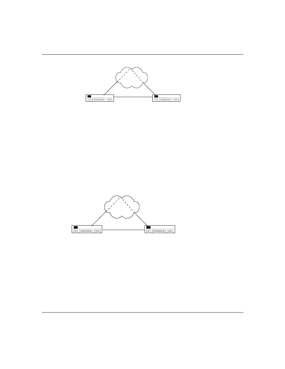
Figure 11-4.
ATM PTOP
Trunking
Trunking allows multiple VLANs to share the same virtual channel connection
(VCC) using either Permanent Virtual Connections (PVCs) or Switched Virtual
Connections (SVCs). Unlike PTOP, VLAN information is passed across ATM
thereby simplifying configuration.
Figure 11-5.
ATM Trunk
*When configuring a SVC connection, ensure the correct PTOP indexes are mapped to the switch you are connecting to.
**When configuring a PVC connection, ensure the VCI values are identical on the switches you are connecting to.
*** When configuring PVC connections through an ATM switch, ensure the bi-directional path is established per port/interface on the ATM switch.
****Valid PTOP index ranges from 0 through 15.
*****When configuring PVC, valid VCI values begin with 32.
H i S p e e d s w i t c h
H i S p e e d s w i t c h
SVC or PVC
VLAN 1: VCC 501
VLAN 2: VCC 502
VLAN 1: VCC 501
VLAN 2: VCC 502
PVC
*When configuring a SVC connection, ensure the correct PTOP indees are mapped to the switch you are connecting to.
**When configuring a PVC connection, ensure the VCI values are identical on the switches you are connecting to.
*** When configuring PVC connections through an ATM switch, ensure the bi-directional path is established per port/interface on the ATM switch.
****Valid Trunk index ranges from 0 through 31.
*****When configuring PVC, valid VCI values begin with 32.
H i S p e e d s w i t c h
H i S p e e d s w i t c h
SVC or PVC
VLAN 1 & VLAN 2: VCC 501
VLAN 1 & VLAN 2: VCC 501
PVC