Ascom, Internal links and fuses – ATL Telecom AM2048 User Manual
Page 38
ascom
telecom
USER GUIDE
AM768A/AM2048A
38
Issue 8
6.
Internal Links and Fuses
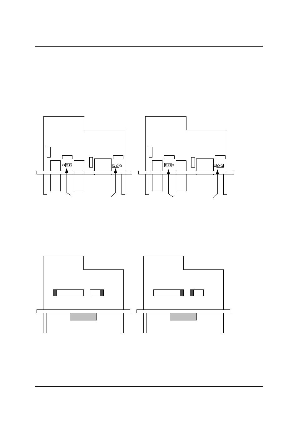
6.1 G.703 Plug In Module
The following diagrams show the location of the internal hardware links.
In all cases the factory default setting is shown on the left.
The 75ohm G.703 receiver and the 120 ohm cable screen may be optionally connected directly to
ground or to ground via a capacitor. The fuses FS1 to FS4 are used to protect the circuit against the
transverse application of mains.
6.2 X.21 Plug In Module MK I
The X.21 module may be configured as a DCE or DTE.
In both modes, the receive clock, data and byte timing circuits may be terminated in 120 ohms.
FS1
FS4
FS2
FS3
FS1
FS4
FS2
FS3
Cap to Ground
Direct to Ground
DCE
DTE
Load
Out
Load
In