Ascom, Telecom, User guide – ATL Telecom AM2048 User Manual
Page 31: 3 copper transmission line, 4 optical transmission line, 5 serial control
ascom
telecom
USER GUIDE
AM768A/AM2048A
31
Issue 8
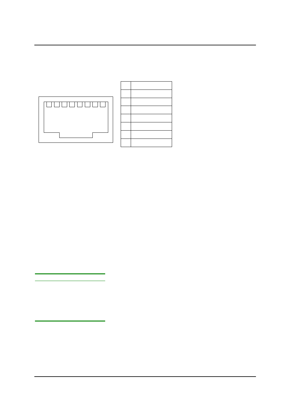
5.3 Copper Transmission Line
The line interface connector on the unit is an 8-way RJ45 socket.
The line cable supplied is a standard 3 metre screened Category 5 cable with an 8 way RJ45 plug on
each end.
Ascom part number
6/910/000/425 (See Appendix B)
5.4 Optical Transmission Line
The rear panel optical connector is either FC/SPC, ST or SC. For ordering information see Appendix
B. Connectors plugged into this port should be clean and should have a return loss better than –35dB.
The dust cap should be fitted when the unit is not connected to the line. The optical output from this
port is –5dBm (±2dB) at 1310nm.
5.5 Serial Control
A VT100 compatible terminal can be plugged into the 9-way D-type on the rear panel.
The socket is wired to allow a straight connection to a PC serial port. The serial cable must have pins
2, 3, 4, 5 and 6 connected.
For a full description of the menu system, refer to the ‘VT100 Management User Guide’.
The serial port setting is 19.2Kbaud/s, 8 bit, no parity, 1 stop bit, Xon/Xoff flow control.
The RS232C interface complies with the CCITT V24/V28 standards. The maximum length of cable
between communicating devices is limited to 15.2m (50ft).
Pin #
Function
1
2
Receive cct 104
3
Transmit cct 103
4 DTR
5
Ground cct 102
6 DSR
The serial control cable can be ordered from Ascom, (See Appendix B)
Serial Cable Assembly-
Ascom Part Number
CABLE 9 WAY SERIAL
6/910/000/429
1
3
2
4
6
5
PANEL VIEW
1
2
4
5
6
Line 1 A
Line 1 B
Line 2 A
Line 2 B
Line 3 A
Line 3 B
7
8
3
7
8
n.c.
n.c.