Ascom, System overview, Telecom – ATL Telecom AM2048 User Manual
Page 10: User guide, 1 copper transmission
ascom
telecom
USER GUIDE
AM768A/AM2048A
10
Issue 8
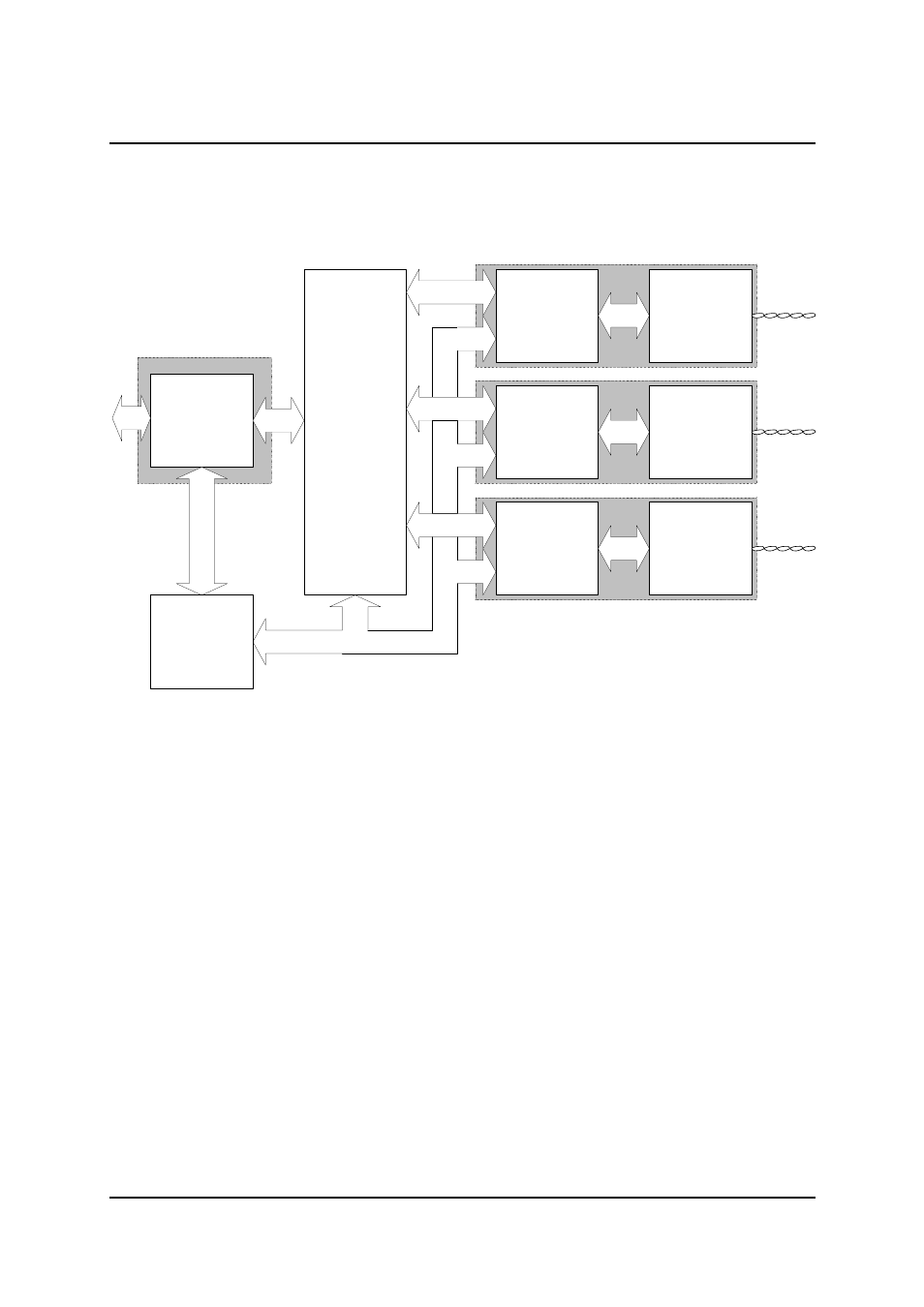
3. System Overview
Primary Rate
Interface
ascom
HDSL
Interface
Chip
DSP
Chip
Transceiver
Analogue
Interface
DSP
Chip
Transceiver
Analogue
Interface
DSP
Chip
Transceiver
Analogue
Interface
Micro
Controller
Pair 1
Pair 2
Pair 3
G703
75/120
ohms
User Interface Module
Transmission Modules
Figure 2 Copper System Block Diagram
3.1 Copper Transmission
The copper system is intended for operation on 2-wire local telephone network circuits, such as those
meeting BT EPS-9 (Note: the DSLU requires between one and three such circuits). It will operate
satisfactorily on unloaded lines having a wide range of characteristics; bridge taps can be tolerated,
dependent upon their characteristics. Although, the system requires a baseband circuit, a continuous
loop at DC is not required. The system can transmit data at rates between 64k and 2048k.
For the copper system, echo cancellation is used to eliminate the unwanted reflections of the
transmitted signal from the receiver input.
The line is connected to the transmission circuit via a line transformer, which acts as a balun and
provides isolation; there is surge protection across the transformer line connections. The transmission
circuit utilises a custom IC and a number of proprietary components to perform the signal processing
described above.
When more than one transmission line is in operation, each transmission system operates with the
same bit rate derived from an oscillator in the master unit.