6 electrical connection, 1 bus termination, 7 canopen interface – ifm electronic JN2100 v.2.0 User Manual
Page 7: 1 canopen functions
UK
Inclination sensor JN
7
6 Electrical connection
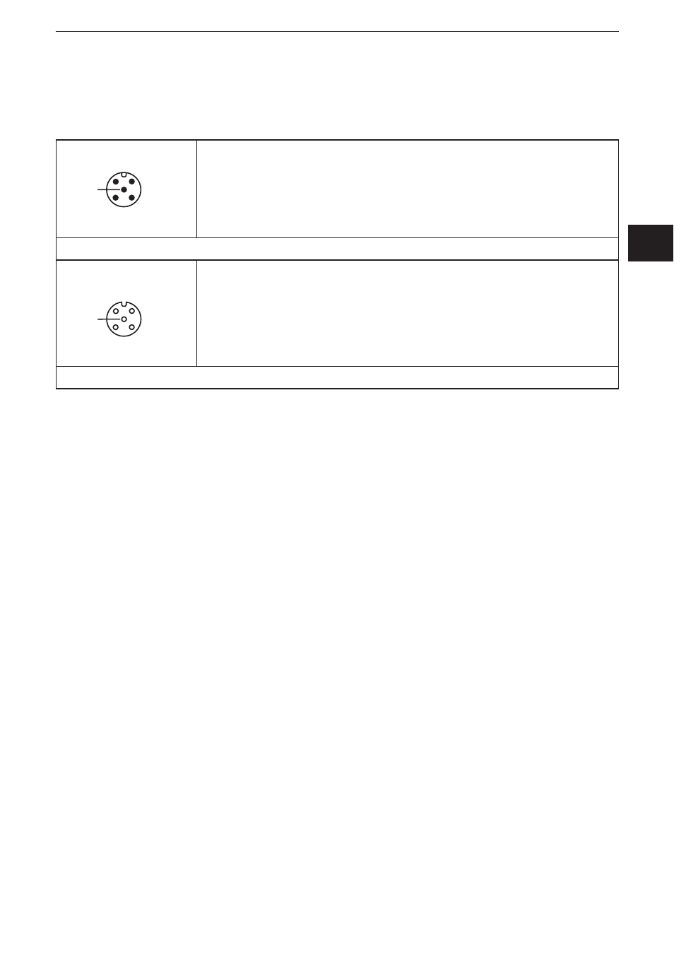
The inclination sensors are fitted with two round 5-pole M12 connectors (A-coded)�
The pin connection corresponds to CiA DR-303-1�
4
2
1
3
5
1: CAN_SHLD shield
2: CAN_V+ supply voltage 24 V DC
3: CAN_GND GND
4: CAN_H H bus cable
5: CAN_L L bus cable
M12 connector CAN-In
3
1
2
4
5
1: CAN_SHLD shield
2: CAN_V+ supply voltage 24 V DC
3: CAN_GND GND
4: CAN_H H bus cable
5: CAN_L L bus cable
M12 socket CAN-Out
6.1 Bus termination
The inclination sensors have an internal terminating resistor → chapter SDO
register�
7 CANopen interface
The inclination sensors have a standardised CANopen interface to CiA DS-301
and a device profile to CiA DSP-410� All measured values and parameters can be
accessed via the object directory (OD)� The individual configuration can be saved
in the internal permanent memory (EEPROM)�
7.1 CANopen functions
The following CANopen functions are available:
● Two transmit data objects (TPDO1, TPDO2) in four possible operating modes:
– individual check via a remote transmit-request telegram (RTR)
– cyclical transmission per interval time
– synchronised transmission after reception of a SYNC telegram
– a service data object (default SDO)
● Error messages per emergency object (EMCY) with support of the:
– general error register
– manufacturer-specific register
– error list (pre-defined error field)
● Monitoring mechanisms heartbeat and node guarding/life guarding