4 quadrant correction (2040h) – ifm electronic JN2100 v.2.0 User Manual
Page 20
Inclination sensor JN
20
The teach operation can, for example, be as follows:
The measured object with the non-aligned inclination sensor is brought into a
known horizontal position� In this position the teach function is carried out, thus
defining the new reference system� All provided angle values then refer to this new
reference system�
Even with an inclination sensor which is installed at an angle note that the x axis (xs axis) of the
sensor is parallel to the xbzb plane of the requested reference system�
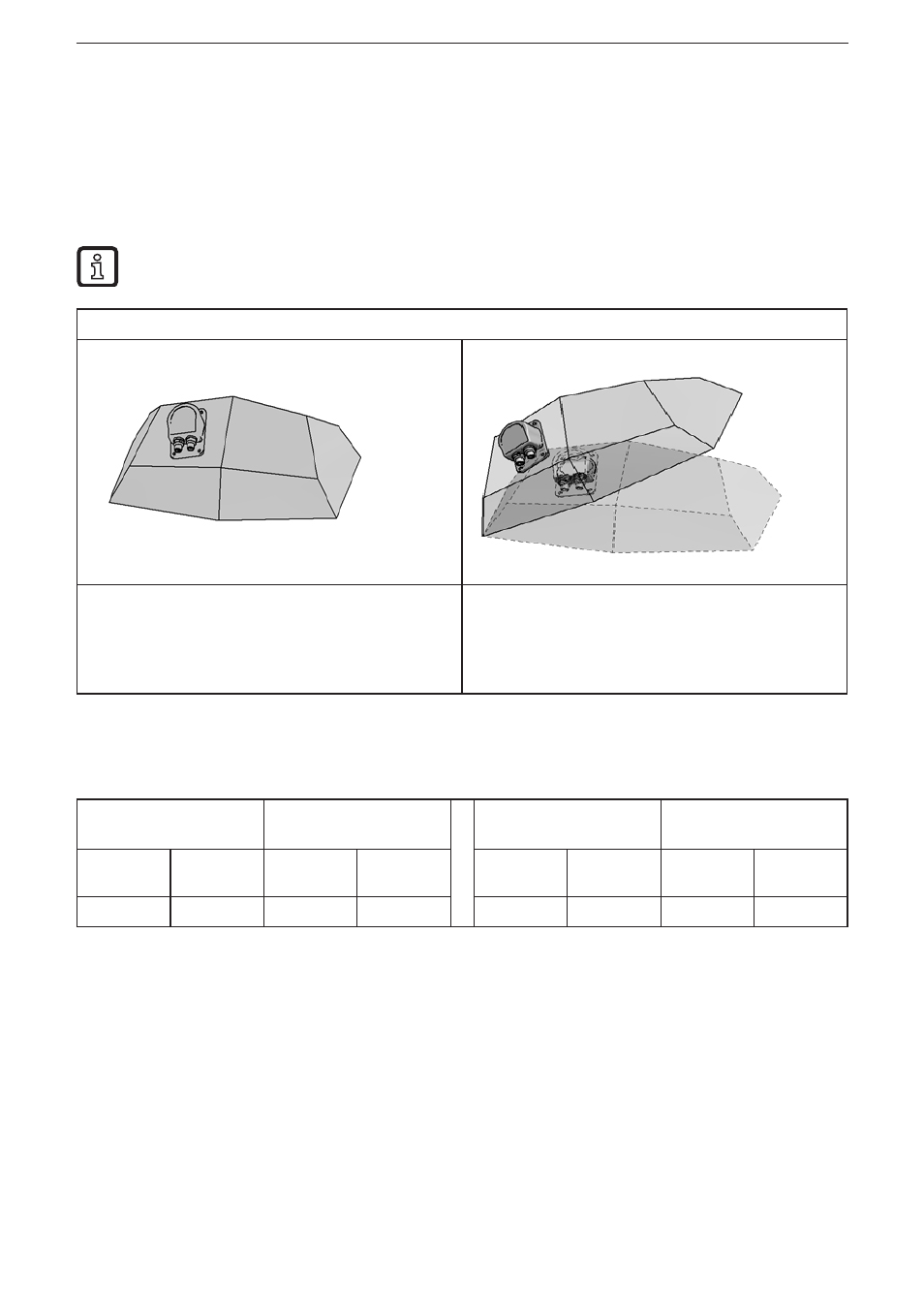
Explanatory example
Inclination sensor installed at an angle in the
coordinate system of the workpiece� The coordinate
system of the sensor is transferred to the coordinate
system of the workpiece by teaching the sensor
when the workpiece is horizontally aligned�
The raw data of the sensor is indicated in the
coordinate system of the sensor�
In teach mode the data is converted into the
coordinate system of the workpiece�
The example shows a rotation of 30° about the y axis of the coordinate system of
the workpiece�
Perpendicular angle
without teach
Teach mode
Perpendicular angle
without teach
Teach mode
Longitudinal
angle value
Lateral
angle value
Longitudinal
angle value
Lateral angle
value
Longitudinal
angle value
Lateral angle
value
Longitudinal
angle value
Lateral angle
value
-13�2°
-29�3°
0°
0°
-45�5°
-29�5°
-30°
0°
7.8.4 Quadrant correction (2040h)
Quadrant correction means an extension of the angle indication to the measuring
ranges
±
180° (corresponds to 2040h = 1) or 0���360° (corresponds to 2040h = 2)�
The following conditions apply to the different angle calculations:
Perpendicular angle: longitudinal (x) and lateral (y) are corrected
Euler: only lateral (y) is corrected
For the gimbal angle the roll angle is corrected�
Gimbal X: longitudinal x (pitch angle), lateral y (roll angle)
Gimbal Y: longitudinal x (roll angle), lateral y (pitch angle)