7 node id (2000h) and baud rate (2001h), 8 limit frequency digital filter (2043h) – ifm electronic JN2100 v.2.0 User Manual
Page 18
Inclination sensor JN
18
Explanatory example
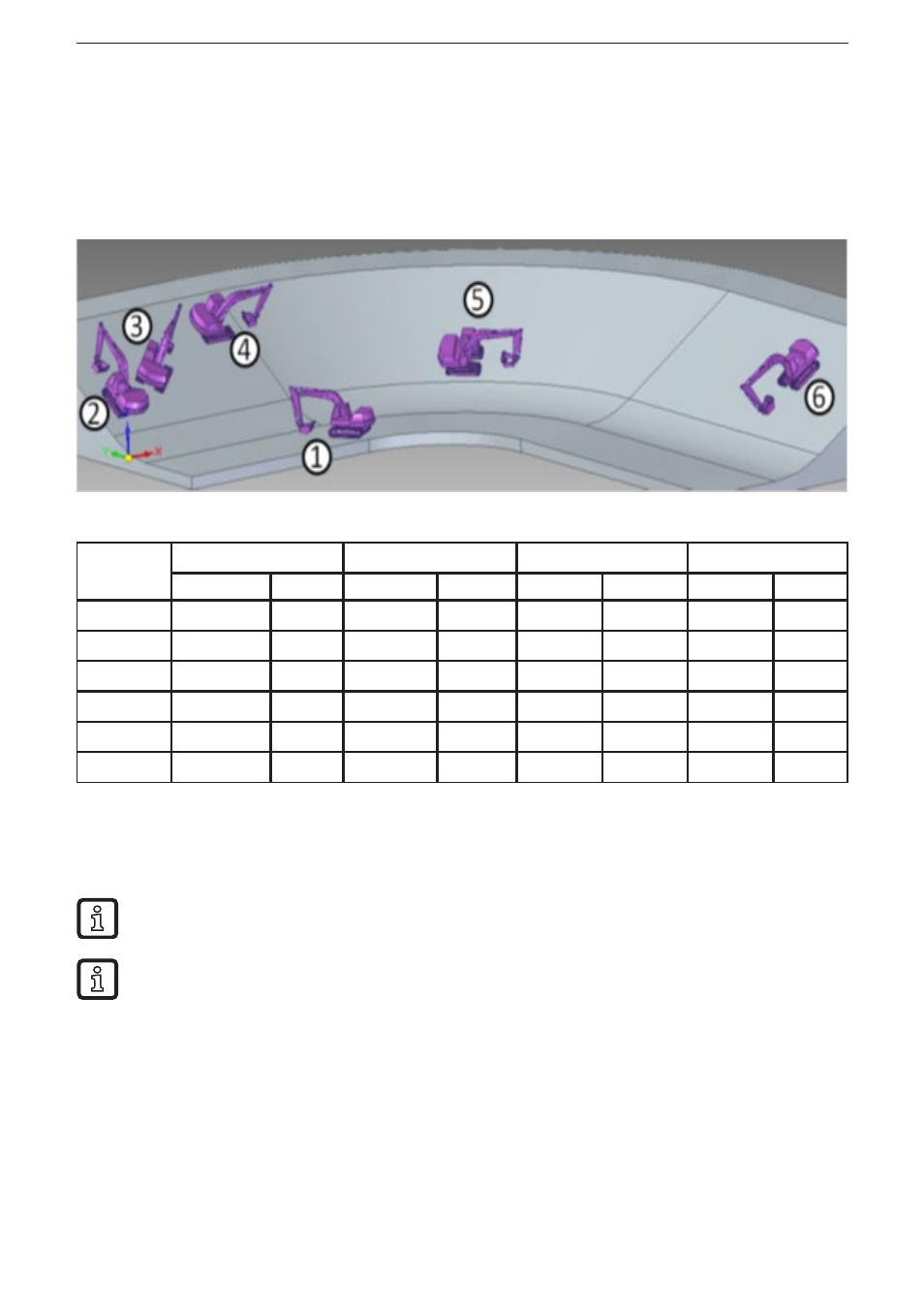
The different angle definitions will be illustrated using a simple example� An
excavator moves up and down an embankment (illustration)� The embankment is
angled at 30°� The inclination sensor is installed so that the x axis of the sensor
shows in driving direction of the excavator�
Excavator
position
Perpendicular angle
Euler
Gimbal X
Gimbal Y
Longitudinal
Lateral
Longitudinal
Lateral
Longitudinal
Lateral
Longitudinal
Lateral
1
0°
0°
undefined
0°
0°
0°
0°
0°
2
-30°
0°
0°
30°
-30°
0°
0°
-30°
3
-20°
20°
45°
30°
-20°
22°
-22°
20°
4
0°
30°
90°
30°
0°
30°
30°
0°
5
0°
30°
90°
30°
0°
30°
0°
30°
6
30°
0°
180°
30°
30°
0°
30°
0°
7.7 Node ID (2000h) and baud rate (2001h)
In the case of a change node ID and baud rate do not become effective until after
a reset (reset application, reset communication or hardware reset)�
After a reset all COB IDs are recalculated and set according to the pre-defined connection set�
The following baud rates [Kbits/s] are supported: 10, 20, 50, 125, 250, 500, 800, 1000�
7.8 Limit frequency digital filter (2043h)
With the sensor it is possible to make continuously arising angle values insensitive
to external interfering vibrations�
Using a configurable filter interfering vibrations can be suppressed� The limit
frequency is individually adjustable between 0�5���25 Hz (25 Hz corresponds to a
deactivated FIR filter)� The digital filter which is implemented in the sensor is an
eighth-order Butterworth low pass filter�
Values of 0 (deactivate filter) up to 4 (0�5 Hz) are allowed�