Microtel Series 500 User Manual
Page 36
29
IV.C.13.
Real Time Clock
The system contains a clock device which retains the time of day, day of week, and the
calendar month and day. To program the Real Time Clock (RTC) cursor to the RTC
value on the System Status Screen (pressing HALT will return control to the System
Status Screen), and select if for editing. The day of the week (Sun, Mon, Tue, etc.) is
automatically determined by the system after the entry of a valid date. The cursor
control keys should be used to move freely to the characters which need to be altered.
Exit the RTC programming mode by cursoring away from the field.
IV.D.
I/O Option Card Programming
IV.D.1
Digital Input Channel Programming
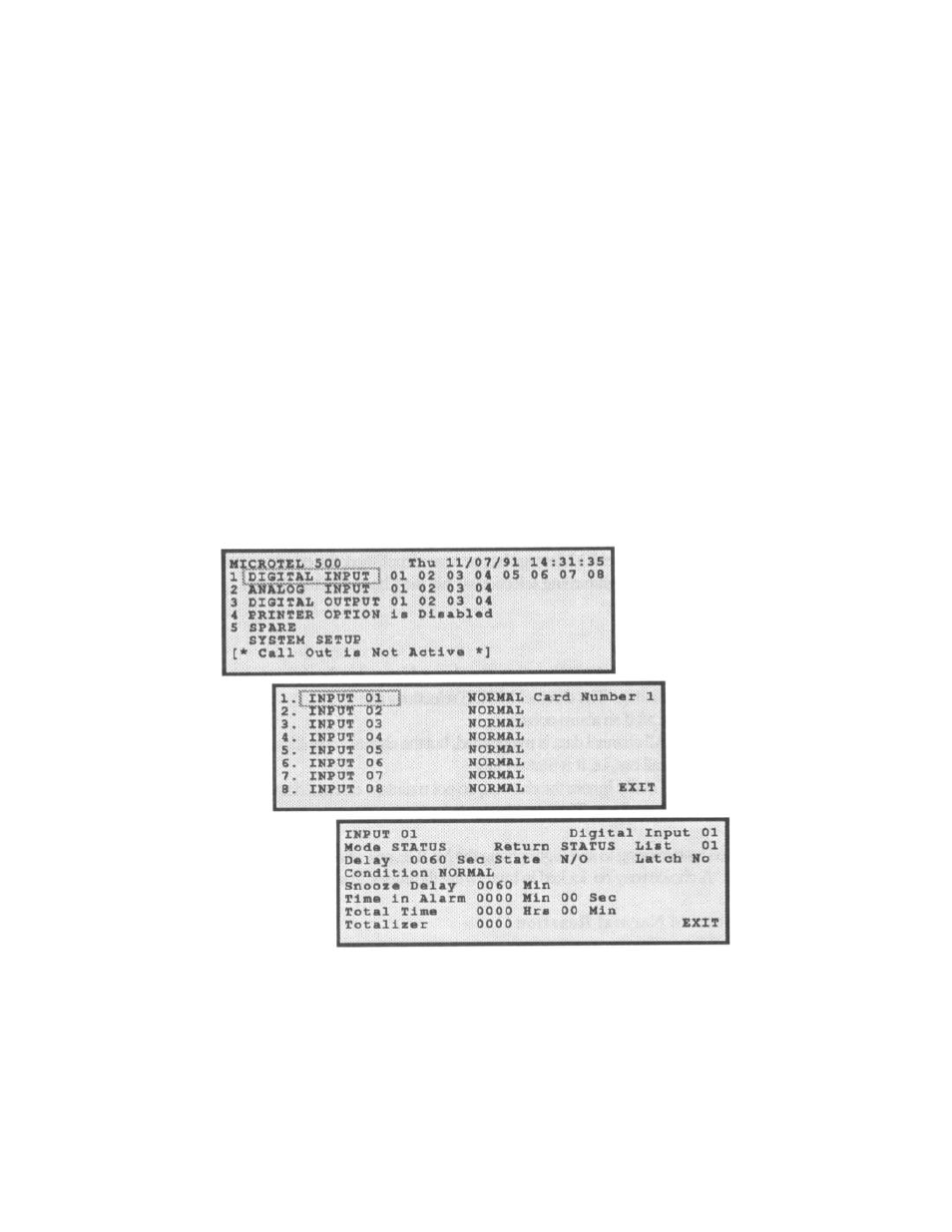
To configure each of the eight Digital Input channels located on each Digital Input
Option Card, that I/O Card must be selected from the System Status Screen. Press
Halt to return to the System Status Screen. Next use the cursor key to access the
Setup Screen for the I/O Card. Following the selection of a particular Digital Input Card,
highlight and select the digital Input Channel to be programmed.
IV.D.1.a. Digital
Input
Channel ID Text Label
The Digital Input Channel ID Text is the name given to the selected fault channel in its
monitoring application. The name may be up to 16 alpha-numeric characters in length.
The default Channel ID Text for a Digital Input Channel is INPUT XX (where XX=00 to
40).