Assembly object instances – Hardy HI 1756-nDF User Manual
Page 29
25
●
●
●
●
●
Chapter 4
Assembly Object Instances
1. Input Assembly (from 1756 nDF to PLC).
An area where the 1756 nDF module writes its data such as Net, Gross, FR to the PLC.
The input assembly is an array of 16 floats, with 8 devoted to the 1st channel and the next
8 devoted to the 2nd channel.
The rate of change and the gross and net weights are always visible in the input table, for
each weigh scale.
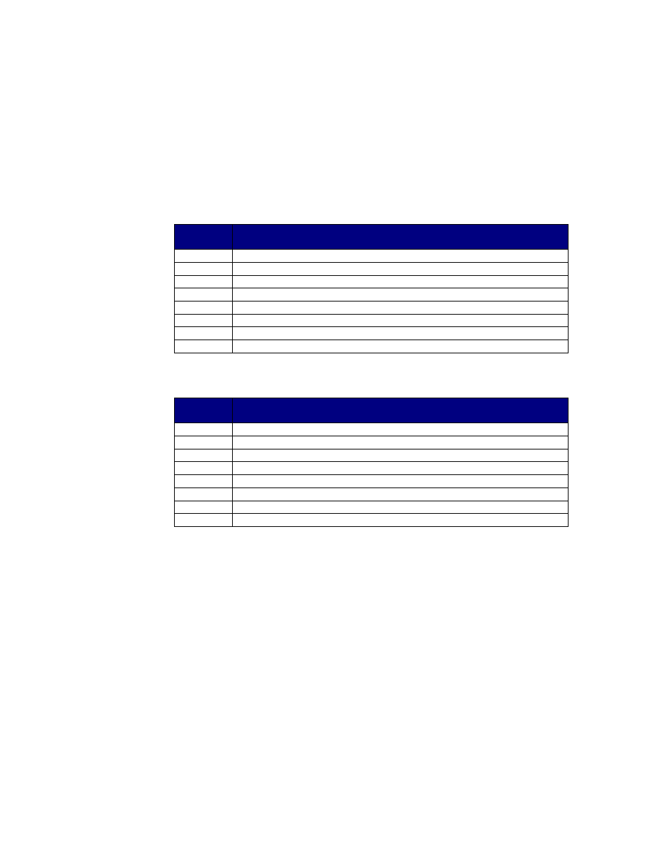
Input table
offset
Content
0
Command (echoes the command given in the Output Table. See below)
1
Command Status (see below)
2
Parameter value, in read and write commands
3
Target Value for relay A (TA)
4
Gross weight
5
Net weight
6
Rate of change
7
STATUSWORD
Input Assembly for Weigh Scale 1
Input table
offset
Content
8
Command (echoes the command given in the Output Table. See below)
9
Command Status (see below)
10
Parameter value, in read and write commands
11
Target Value for relay A (TA)
12
Gross weight
13
Net weight
14
Rate of change
15
STATUSWORD
Input Assembly for Weigh Scale 2 (for HI 1756 2DF only)
2. Output Assembly (from PLC to 1756 nDF)
Dedicated area where PLC writes parameters to the 1756 nDF; these values are read by
the 1756 nDF as scheduled by the RPI. The output assembly defaults to an array of floats.
The output table consists of 16 float values, of which the first 8 float values apply to the
1
st
channel, and the next 8 float values apply to the 2
nd
channel.
The first float value of the 8 is the “command” value. The interpretation of the next 7
values depends on the command being given.
Default Output Table Description
These commands are zero, tare, write nonvolatile, reload nonvolatile, cal low, cal high,
C2 cal. These commands do not require any of the 7 other float values. These commands
will use the default output table format.