Chapter 4 configuration, Power check, Leds – Hardy HI 1756-nDF User Manual
Page 15
11
●
●
●
●
●
Chapter 4
Chapter 4 Configuration
● ● ● ● ●
Chapter 4 covers the settings used to prepare the controller for calibration and operation.
The Setup procedures require Allen-Bradley’s RS Logix 5000, Allen-Bradley RSLinx™
or RSLinx™ Lite.
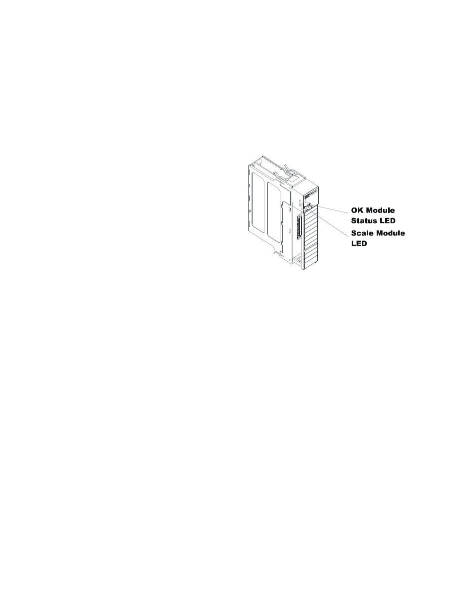
Power Check
To make or change settings, there
must be power to both the PLC and
the module. Verify that the LEDs
are lit for normal operation.
Module LEDs
LEDs
Scale Data LEDs
Flashing Green
Dispenser/Filler is active (on)
Steady Green Running
(Normal)
Steady Red
Device Failure. Contact HI Customer Support
Flashing Red
Read Convert Error.
LED is Off
Channel is Inactive
OK Module Status LED
Brief Steady
During power up the LED lights Red for about one second.
Flashing Green
In Program mode. (Normal)
Steady Green
In Run Mode. (Normal)
Steady Red
Device Failure. Contact HI Customer Support.
Flashing Red
Communication Error.
At power-up, the module runs through an initial self-diagnostic check. If the module does
not have valid calibration data the scale data LED will flash green at a rate of about once
a second.
The door will open to the right revealing two groups of connectors and one red button for
C2 calibration at the “cal low weight” parameter value. The number of pins in the
connector will depend on the number of channel options obtained. The left group of
connectors will be for weigh scale inputs and the group of connectors on the right will be
for relay I/O.