IKA C 1 Package 1/10 User Manual
Page 9
9
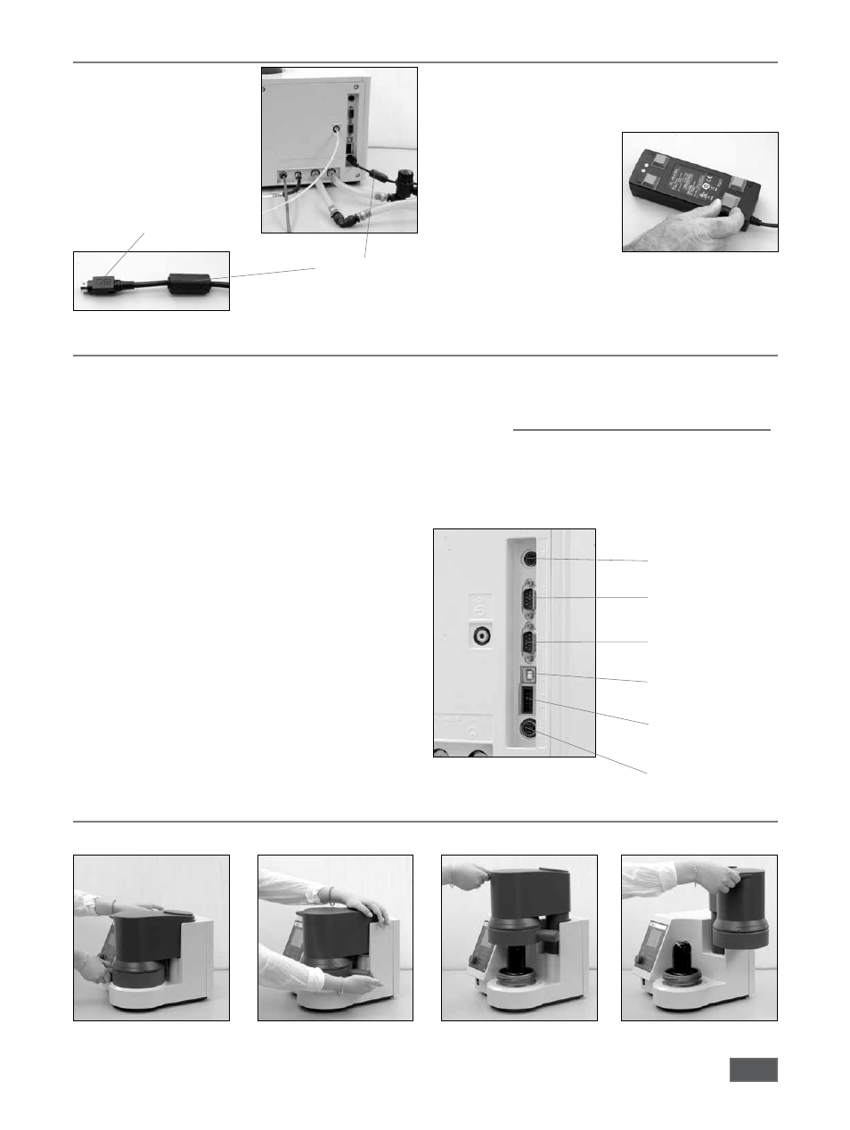
Power supply unit connection
1. Connect the power supply
connecting cable (24V)
NOTE: Note the correct inser-
tion position (flat side
of the connector
pointing to the right).
Connecting cable
The desktop power supply (scope of delivery) must not be placed
flat on the laboratory table. It must be protected against moisture
and water penetration and must not be wet.
2. Tape the supplied rubber feet
to the power supply.
Place the power supply on the
rubber feet.
Connect the connection cable
to the DC power supply to
your supply network
(100-240V AC 50/60Hz).
flat side of the connector
Connection of peripherals
Heating:
Control output for the connection of the IKA
®
heating.
Scale:
RS232 interface for connection of a scale
(Mettler, Ohaus, Sortorius, Kern)
Interface parameters:
Baud rate: 1200
Data its:
7
Parity:
odd
Stop its:
1
Handshake: none
PC/Printer: RS232 interface for connecting a PC to control
the C1 (CalWin C6040) or a printer to output the
measurement data.
Interface parameters:
Baud rate: 9600
Data its:
8
Parity:
none
Stop its:
1
Handshake: none
USB-B:
USB device interface for connection the calori-
meters to the PC (CalWin C6040).
The connection simulates a serial interface on the
PC.
Installation:
After the C1 was connected with the supplied
data cable to the PC, the C1 tells the Windows
operating system, which device driver is required.
24V =
Programming (Prog)
interface
USB-B (USB)
PC / Printer (PC)
Scale (balance)
Heating (ext)
This driver can be downloaded from the
IKA website.
Find your driver at the following website:
http://www.ika.com/ika/lws/download/stmcdc.inf
Programming- (only for service)
interface:
24V=
24V Voltage input for the included power
supply table.
Handling the unit
1. Opening the unit
The closing of the unit in the reverse order
Q
h
h
1
2
Q
C1 092014