8 external peripheral interface connectors, 1 lcd panel connection, 2 ethernet connection – IEI Integration PPC-5xxx-9455 v1.00 User Manual
Page 81: Xternal, Eripheral, Nterface, Onnectors, Figure 4-23: arm mount retention screw holes
PPC-5xxx-9455 Panel PC
Page 63
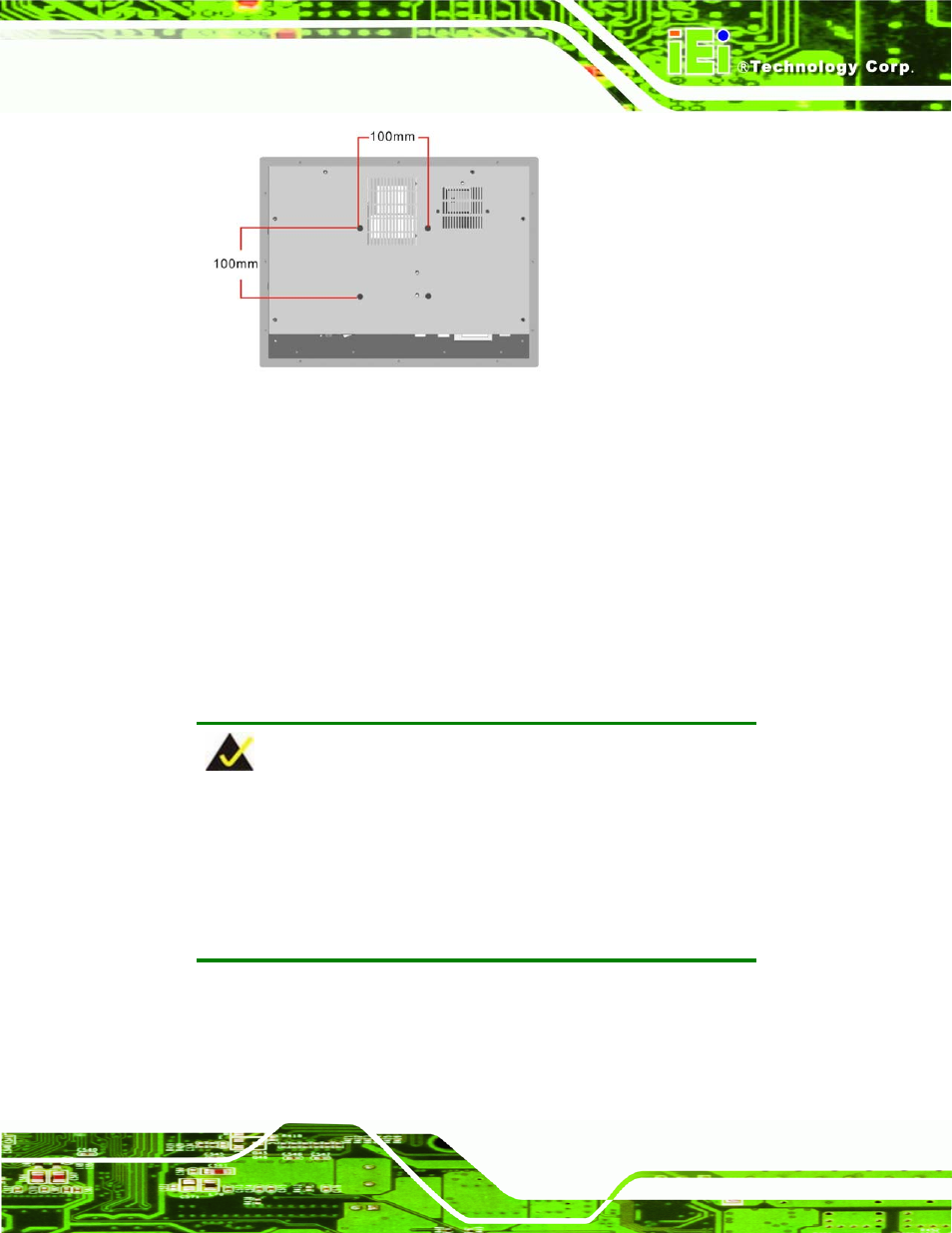
Figure 4-23: Arm Mount Retention Screw Holes
Step 4:
Secure the PPC-5xxx-9455 to the interface pad by inserting four retention
screws through the mounting arm interface pad and into the PPC-5xxx-9455 flat
panel PC.
Step 0:
4.8 External Peripheral Interface Connectors
4.8.1 LCD Panel Connection
A conventional CRT VGA 15-pin female D-SUB connector is located on the bottom panel
to connect the PPC-5xxx-9455 flat panel PC to a second monitor.
NOTE:
To use the dual screen option, please configure this option in the Intel®
Extreme Graphics configuration settings. To do this, open the Control
Panel, locate the Intel® Extreme Graphics icon and click on it. Once
opened, an option for Multiple Display is available. Select this option
and select notebook as the primary device.
4.8.2 Ethernet Connection
The two external peripheral interface RJ-45 connectors can be connected to an external
LAN to provide Internet connectivity to the flat panel PC.