5 jumper settings, Umper, Ettings – IEI Integration PPC-5xxx-9455 v1.00 User Manual
Page 59
PPC-5xxx-9455 Panel PC
Page 41
4.5 Jumper Settings
NOTE:
These jumper settings and the jumper locations are described in detail
in the user manual that came with the POS-9455 motherboard. Please
refer to the manual for more detailed descriptions of the jumper
settings.
NOTE:
A jumper is a metal bridge that is used to close an electrical circuit. It
consists of two metal pins and a small metal clip (often protected by a
plastic cover that slides over the pins to connect them. To
CLOSE/SHORT a jumper means connecting the pins of the jumper
with the plastic clip and to OPEN a jumper means removing the plastic
clip from a jumper.
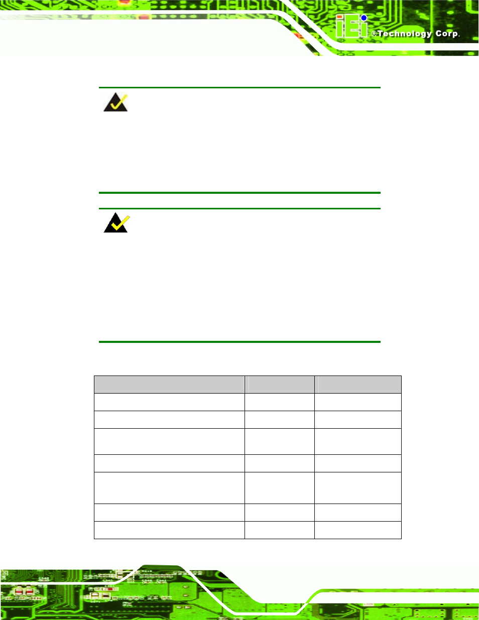
The POS-9455 comes with fifteen jumpers (Table 3-1).
Jumper
Type
Label
AT/ATX power selection
2-pin header
AT_PWR_SW1
Clear CMOS
3-pin header
JP2
Monitor Setup
8-pin header
JP1
CompactFlash® card setup
2-pin header
JP7
COM port pin-9 setting
6-pin header
JP3, JP4, JP5, JP6,
JP8
COM5 RS-232/422/485 RX select
6-pin header
J2
COM5 RS-422/485 TX select
6-pin header
J3