Veris Technologies 3150 Soil EC Mapping System - Operating Instructions User Manual
Page 43
Pub. # OM17-EC
6-9
2. Inspect nylon insulation slides under coulter-electrode mounting brackets. These nylon
insulators may become worn or brittle, or may slip out from under mounting bracket. Repair
and replace as necessary. Make sure that all electrode coulter U-bolts are properly
tightened to clamp mounting bracket and insulation tightly to frame.
nylon insulation
Figure 3.9
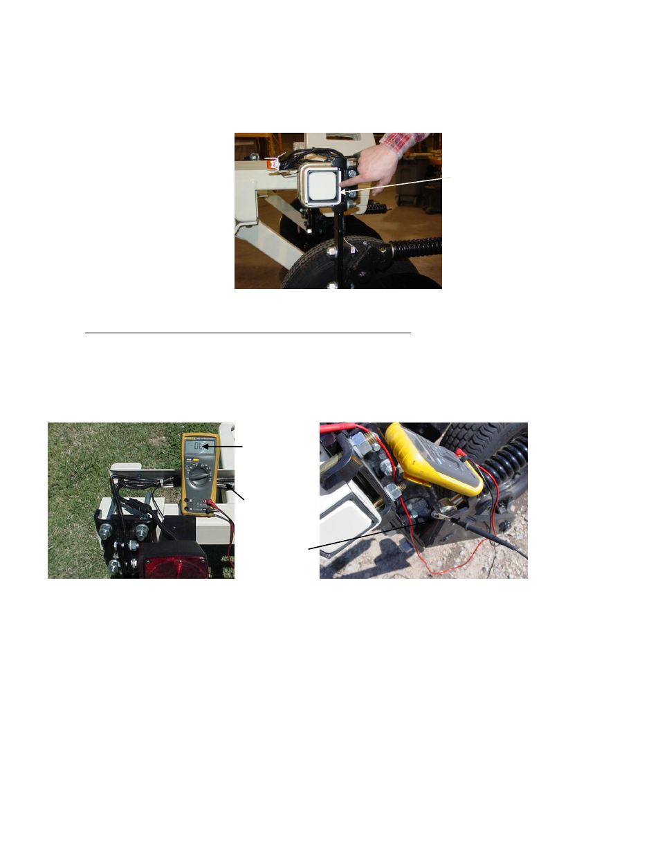
3. Disconnect signal cable from instrument or front of frame. Check so see that no metal part
of the any coulter electrode is in contact with the implement frame. This may be by visual
inspection or by connecting one lead of an ohmmeter to the individual coulter electrode, and
the other to a grounded fastener on the frame. If the coulter electrode is properly isolated,
no reading will be obtained. Make sure that all electrode coulter clamp bolts are properly
tightened to prevent lateral movement of the coulter electrode.
Figures 3.10 a and b
no
continuity
grounded
bolt
coulter
terminal