Veris Technologies 3150 Soil EC Mapping System - Operating Instructions User Manual
Page 15
Pub. # OM17-EC
2-3
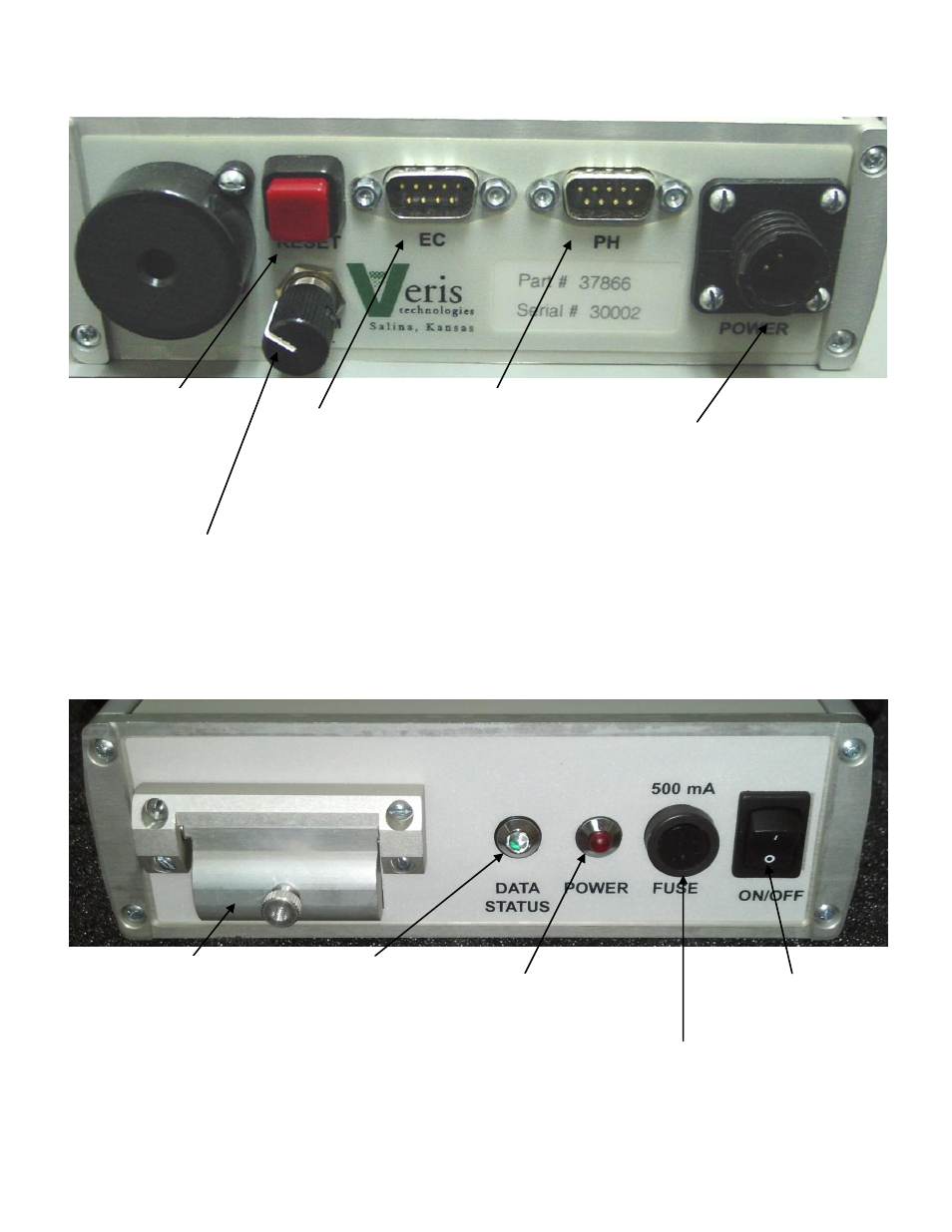
Figure 7. DataLogger (front)
Data Status:
When lit, this green
LED indicates data
is being recorded to
memory card. If not
lit, EC values are
negative or GPS
signal not received.
Power:
When lit, this red
LED indicates
Sensor DataLogger
is powered up.
Memory Card slot:
Formatted SD memory
card must be installed
when booting up, and
at all times data is
being collected. See
Proc. #6 for formatting
instructions.
Power port:
The Sensor DataLogger is
shipped with an accessory
power cord. If an alternative
connection is desired, make
sure that the unit is properly
connected to a power
connection that is not
controlled by the ignition
switch. If connecting directly
to the battery, we suggest a
3-amp in-line fuse is
installed between the battery
and the instrument.
EC:
Serial cable
from EC
Surveyor
attaches here.
pH:
Serial cable from pH
Controller (MSP
only) attaches here.
Reset
button:
Can be used
to reboot
DataLogger
Alarm Vol:
Used to adjust
volume of auditory
alarm
Fuse:
This allows the fuse
to be replaced, with
a 500mA Fastblow
fuse, if blown.
On/Off:
Turns power to
Sensor DataLogger
on and off.