Veris Technologies 3150 Soil EC Mapping System - Operating Instructions User Manual
Page 28
Pub. # OM17-EC
4-6
Field Operations--Implement
Checking Electrical Signal Continuity and Electrode Isolation
It is recommended that you perform the Electrical Signal Continuity and Electrode Isolation test
procedure before first field use (see Maintenance and Service Procedures 1 and 2). While these
tests were made at the factory, there is the possibility a problem developed during shipping.
Performing these tests on the new implement before it becomes dirty, allows you to get familiar
with the process under ideal conditions. It is strongly advised that you perform this test on a routine
basis (every 10 hours of data collection) to ensure you are obtaining reliable data. KEEP
OHMMETER, TEST LOAD AND TEST BOX WITH THE MACHINE AT ALL TIMES.
Equipment pre-mapping check
Prior to operating the implement for the first time, it is important to check the fasteners
– some may
have loosened during shipment. Routine fastener checking should be done weekly during
mapping season and a walk-around check of the implement components should be done each
day.
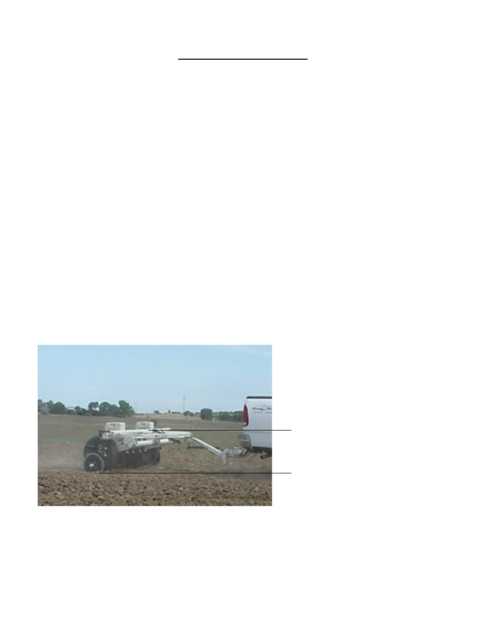
Setting Operating Depth
Begin field operation by lowering unit into soil. For good electrical conductivity, all coulter
electrodes must be in direct contact with moist soil, at all times and in every region of the field. A
depth of 1-
2” (2.5-5 cm) is recommended. To insure this depth is consistently achieved, 400-600
lbs. (180-275 kg) of additional weight are normally required. Veris offers optional weights, or they
can be supplied by the customer. Do not adjust the tension on the coulter electrode springs to
increase soil contact or penetration. They are pre-set at the factory with the proper tension.
Figure 13
operate
implement
parallel to
soil