Veris Technologies 3150 Soil EC Mapping System - Operating Instructions User Manual
Page 29
Pub. # OM17-EC
4-7
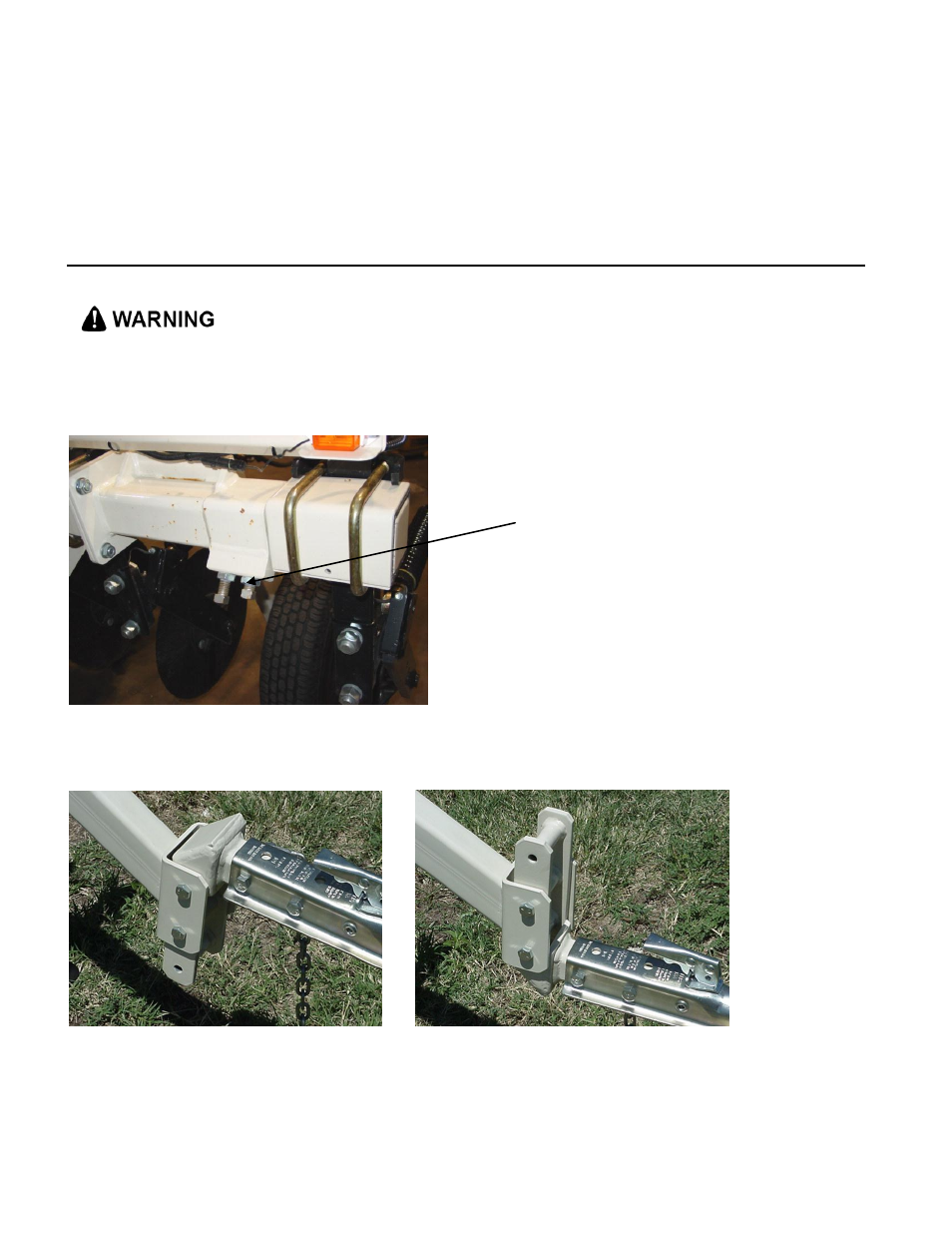
Adjustable Wing Extensions (XA option)
The 2000XA and MSP3150 with XA (Extendable Array): This option allows the re-positioning of
the electrodes to fit various bed and crop configurations. Adjustment is made by loosening the jam
nuts and set screws located on the lower front of each side of the toolbar, adjusting the toolbar
wing extensions, and re-tightening the set screws. Veris suggests setting the toolbars at either the
maximum or minimum setting, not at a point in between. A limiter bolt determines full extension, so
they cannot extend to the point at which the outside coulters disconnect from the main frame.
Important
– do not attempt to combine maps in which two different investigative depths are used.
• Pinch point hazard: to prevent injury, stand clear when raising or lowering any part of the Veris
MSP. Disengage automatic cycling function before working around unit.
• Install all transport locks before transporting or working underneath.
Figure 14
Adjust hitch on implement so implement operates level when coulter electrodes are 1-
2” in the soil.
The hitch is designed with four possible height positions.
Figures 15a and 15b
set screws and
jam nuts