Veris Technologies 3150 Soil EC Mapping System - Operating Instructions User Manual
Page 21
Pub. # OM17-EC
3-3
Installation:
1) Locate power unit in desired location in towing vehicle. If the unit is to be used on a dedicated
unit, we advise anchoring it securely to prevent tipping or damage in rough field conditions.
Mounting holes are located on each side of base.
2) Connect ground (black) power cable to negative post on towing vehicle battery.
3) Connect power (red) cable directly to the positive post on the battery. Quick connect to power
unit.
4) Remove the shipping plug from the reservoir and install breather cap. ( a plug will be installed if
shipped via UPS).
5) Lower implement to the surface and remove ratchet jack. (Note: Cylinder may have been
previously installed at factory).
6) Connect hoses to power unit. Note that the quick couplers are labeled for proper connection.
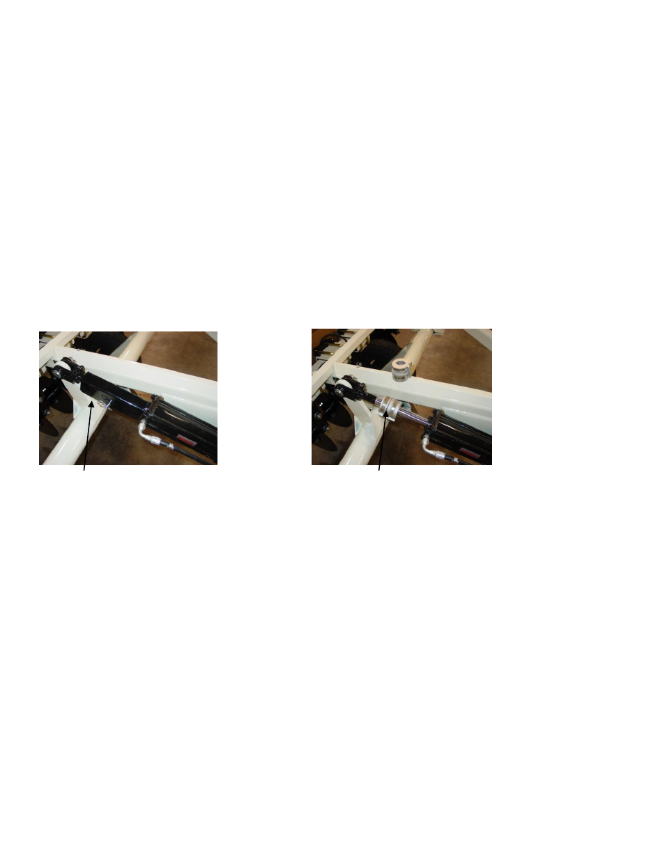
7) Install the cylinder to the implement as shown below, with the rod end to the rear and the
cylinder barrel in the lower position; with the hose fittings outward from the center.
Figure 6
Figure 7
Transport lock
Depth Collars
Operation:
1) The remote control offers simple operation of the power unit. Push button to raise and lower
Route to prevent damage of cable. Never engage power unit with hoses disconnected
– if
so, you may to need to bleed pressure as described below.
2) Be sure to lower the unit only as deep as needed to obtain proper penetration of all six coulters.
Use depth collars provided to set desired operational depth.
3) Due to the design of the implement, it is not necessary to raise the unit during field turns.
4) Prior to road transport, always install the transport lock channel on the cylinder rod.
5) To disconnect the implement from the power unit, install the transport lock and lower the
implement until it rests on the lock. Momentarily bump the control switch upward to relieve
system pressure and disconnect the hoses. Try not to disconnect under pressure, as it will be
difficult to re-connect.
6) Periodically check the fluid level of the reservoir with the implement in the lowered position. It
should be roughly 2” from top of reservoir, with the cylinder rod in the retracted position. Unit is
filled with Mobil 424 hydraulic fluid, and should be filled with compatible fluids of viscosity index
between 100 and 400 ssu.
7) Keep couplers as free of contaminates as possible, and install rubber plugs and caps when unit
is not in use.