Figure 7-7. buffered pulse-width measurement, Period measurement, Period measurement -6 – National Instruments DAQ M Series User Manual
Page 68
Chapter 7
Counters
7-6
ni.com
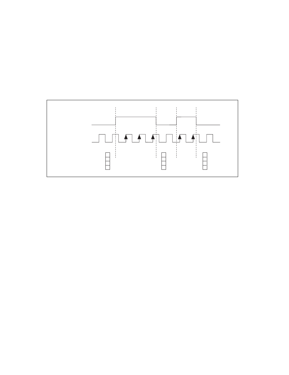
The counter counts the number of edges on the Source input while the Gate
input remains active. On each trailing edge of the Gate signal, the counter
stores the count in a hardware save register. A DMA controller transfers the
stored values to host memory.
Figure 7-7 shows an example of a buffered pulse-width measurement.
Figure 7-7. Buffered Pulse-Width Measurement
Note that if you are using an external signal as the Source, at least one
Source pulse should occur between each active edge of the Gate signal.
This condition ensures that correct values are returned by the counter. If this
condition is not met, consider using duplicate count prevention.
For information about connecting counter signals, refer to the
Period Measurement
In period measurements, the counter measures a period on its Gate input
signal after the counter is armed. You can configure the counter to measure
the period between two rising edges or two falling edges of the Gate input
signal.
You can route an internal or external periodic clock signal (with a known
period) to the Source input of the counter. The counter counts the number
of rising (or falling) edges occurring on the Source input between the two
active edges of the Gate signal.
You can calculate the period of the Gate input by multiplying the period of
the Source signal by the number of edges returned by the counter.
SOURCE
GATE
Counter Value
Buffer
1
0
3
3
2
2
1
2
3
3
2