Chapter 9 isolation and digital isolators, Figure 9-1. general ni 6236 block diagram, Isolation and digital isolators – National Instruments DAQ M Series User Manual
Page 107
© National Instruments Corporation
9-1
9
Isolation and Digital Isolators
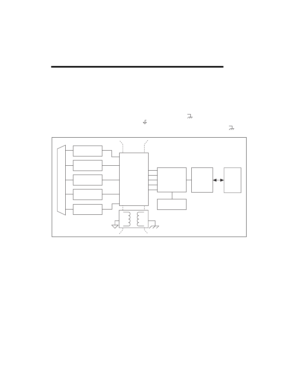
NI 6236 devices are isolated data acquisition devices. As shown in
Figure 9-1, the analog input, analog output, PFI/static DI, and PFI/static
DO are isolated from earth/chassis ground,
, and are all referenced to
the isolated ground,
. The bus interface circuitry, RTSI, digital routing,
and clock generation are all referenced to a non-isolated ground, .
Figure 9-1. General NI 6236 Block Diagram
The non-isolated ground is connected to the chassis ground of the PC or
chassis where the device is installed.
The isolated ground is not connected to the chassis ground of the PC or
chassis. The isolated ground can be at a higher or lower voltage relative to
the non-isolated ground. All analog and digital signals are made relative to
the isolated ground signal.
The isolated ground is an input to the NI 6236 device. The user must
connect this ground to the ground of the system being measured or
controlled. Refer to the
Connecting Analog Current Input Signals
section
of Chapter 4,
, the section of Chapter 5,
Analog Output
Analog Input
PFI/Static DI
PFI/Static DO
Digital
Routing
and Clock
Generation
Bus
Interface
I/O Connector
RTSI
Digital
Isolators
Isolation
Barrier
Bus
Counters