5 i/o expansion power supply, 2 analog input 2 – Infinite Peripherals SCOM-100 User Manual
Page 8
SCOM-100, User guide
8
The circuit displayed on the right side of the page uses an external resistor (Rx) to
measure DC voltage (Vx). Rx and Rin (2K) form a voltage divider. The following table
illustrates the applicable resistor Rx values for different DC voltages:
Vx Rx
Vin
0..1V 0
0
-1V
0..5V
8K, 1/4W
0 -1V
0..30V
58K, 1/4W
0 -1V
0..60V
118K, 1/4W
0 -1V
0..100V
198K, 1/4W
0 -1V
Note: In case of low voltage measurements, use short and shielded wiring to avoid
50Hz (60Hz) line noise inteference.
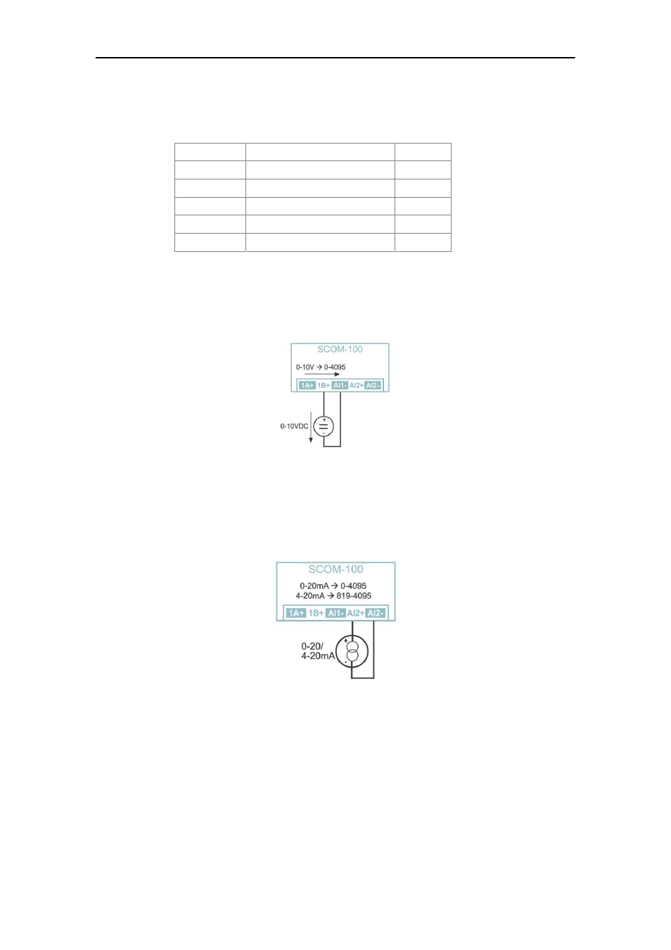
Wiring option: A1B
Wiring option A1B is designed for 0-10VDC signal input through an internal 18K & 2K
voltage divider. The input resistance is 20K.
2.4.2 Analog input 2
Analog input 2 is designed as a current input.
It can be used in conjunction with industry standard current loop transducers &
sensors. Input impedance is 50Ω. The 0-20mA input is converted internally to a digital
raw range of 0-4095.
Note: Applying a voltage source to the current input AI2 may damage the internal 50Ω
input resistor and respectively the entire input circuit.
2.5 I/O expansion power supply
SCOM-100 has two ways to provide power supply for the I/O expansion units.