Wiring, 1 power supply, Digital inputs – Infinite Peripherals SCOM-100 User Manual
Page 6: 3 digital outputs
SCOM-100, User guide
6
2. Wiring
SCOM-100 is a simple device, not requiring special technical background for
configuration and operation. However an electrical technician should undertake the
installation of the device.
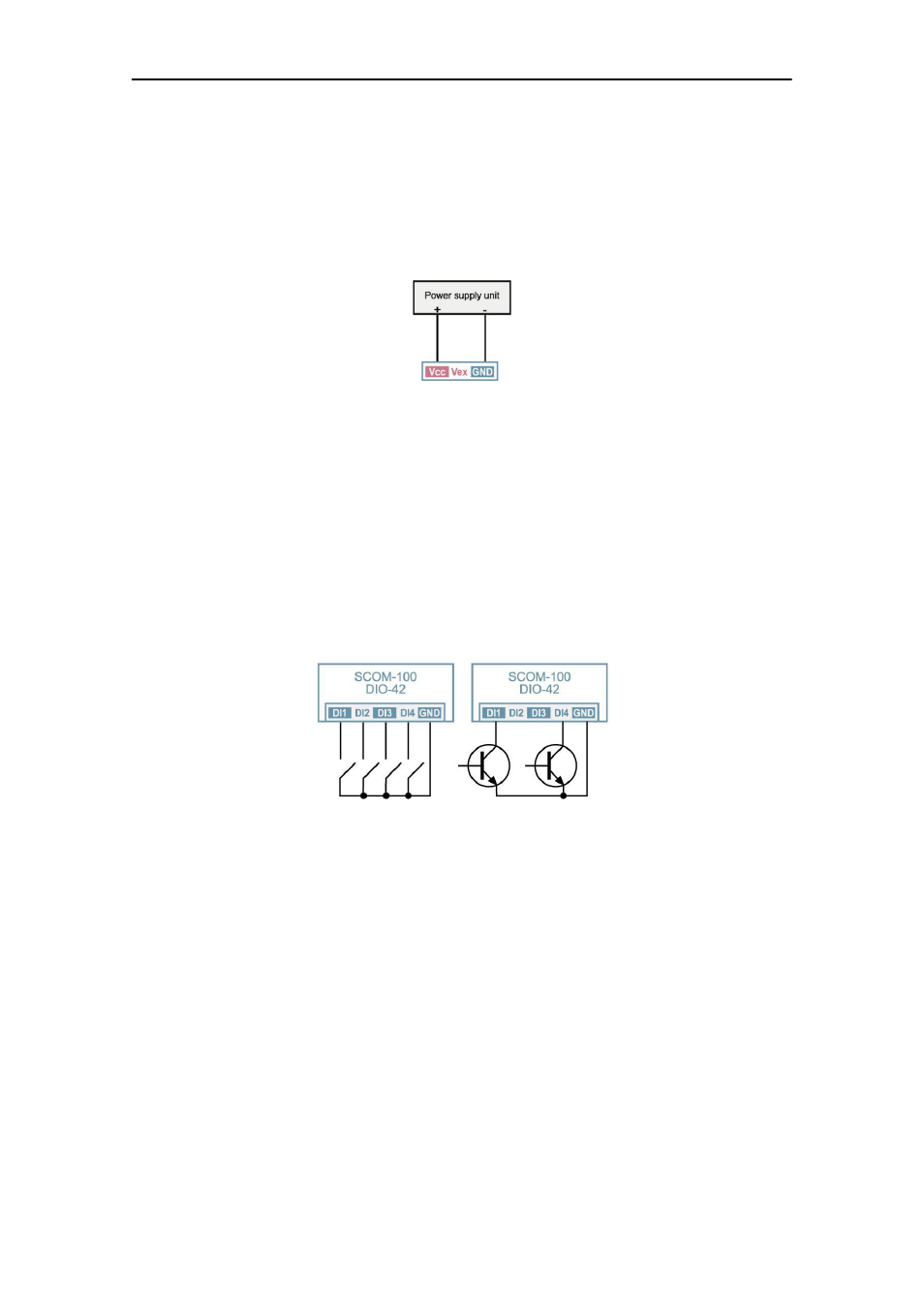
2.1 Power supply
Power supply requirements are:
• SCOM-100-12:
12VDC
+/-15%
• SCOM-100-24:
24VDC
+/-15%
A low ripple power supply output is recommended. Output voltage stabilization is not
required.
See section 9.3.1 for details.
2.2. Digital inputs
SCOM-100 has 4 built in digital inputs, which can be expanded by means of 8 GE-
DIO-42 expansion modules. The digital inputs are wired by means of screw terminals.
The digital inputs can be driven either by switches or transistors (open collector
stages). Transducers with push-pull output are also applicable.
Note: Output voltages higher than +5V or negative voltages (lower than GND) will be
clamped from the comparator input protection zener. The impedance
of the input
circuit is, in this case, 4.7K. An external transducer with 24V output must be
capable of driving a current of 5 mA.
2.3 Digital outputs
SCOM-100 has 4 built in digital outputs, which can be expanded by the DIO-42
expansion modules. The digital outputs are wired by means of screw terminals. Each
output has a normally open contact power relay.