A.2 description – Honeywell SMV 3000 User Manual
Page 163
1/99
SMV 3000 Transmitter User’s Manual
151
A.2
Description,
Continued
Diagram: Typical
Integration Hierarchy
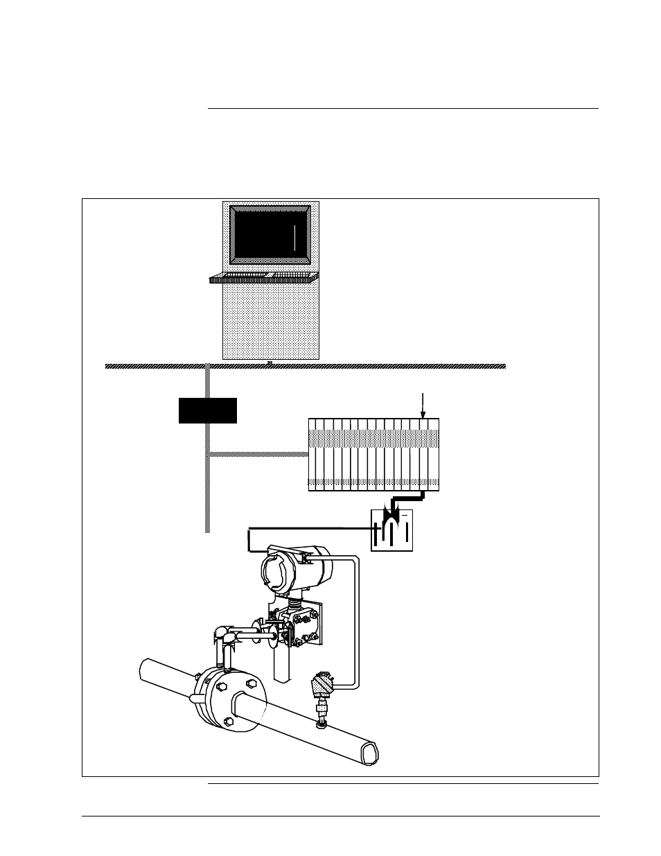
Figure A-1 shows a typical PM/APM/HPM SMV 3000 integration
hierarchy with the transmitter connected to the system through an STI
FTA, and a multivariable STIMV IOP in the PM/APM/HPM.
Figure A-1
Typical PM/APM/HPM SMV 3000 Integration Hierarchy.
SMV3000
Transmitter
Universal Station
Local Control Network
Network
Interface
Module
Universal
Control
Network
PM, APM, or HPPM
Smart Transmitter Interface
MV I/O Processor
STI
FTA
DE/ Digital
Communications Link
Supports up to
16 single PV
transmitters, 4
multivariable
transmitters with
4 PVs each, or
some mix of
single and
multivariable
transmitters that
equals 16 inputs
per IOP