Table 5-9, Table 5-10, Table 5-11 – HP TM 11-6625-2779-14&P User Manual
Page 50
Section V
Model 3555B
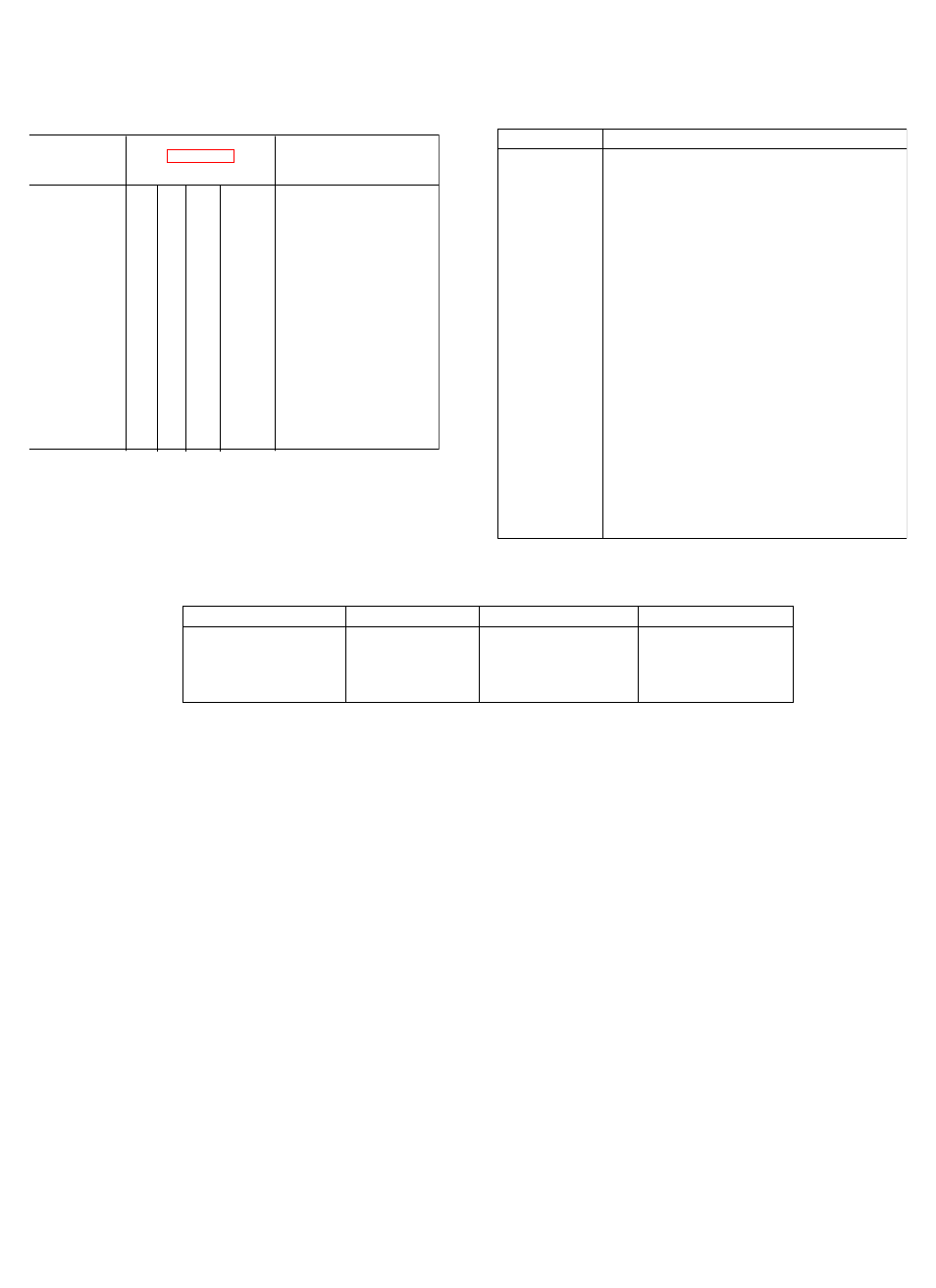
Table 5-9. Range Attenuation and Amplifier Gain
Attenuator Pads Used
Amplifier Gain
Switching
RANGES
1
2
3
4
+30
X
X
X
+20
X
X
X
+10
X
X
0
X
X
-10
X
X
-20
X
-30
X
-40
X
-50
-60
A2R13, A2R14
-70
A2R13
-80
Ranges Affected +30 -20
+30
+20
-60 and -70
If Defective
+20 thru
0
-10
+10 +30
-30
-40
Table 5-11. Factory Selected Values
Designator
Purpose
C4
Adjust balance at 600kHz, 135 BAL
A1C5
Padding capacitor for A1 C4
A1C9
Adjust balance 20kHz, 600 BAL (VF/Nm)
A1C8
Padding capacitor for A1C7
A1C10 and
Frequency response correction for A1TI
A1R12
A1R14
600 BAL, VF/Nm calibration
A3C1
Padding capacitor for A2C12
A3C15
Frequency response, 20Hz, -80dBm, 600
BAL (VF/Nm)
A3R46
Adjust the bias level for A3Q10 (-10V at +
side of A3C24)
A3R72
Response, 20Hz, 600 BAL (VF/Nm)
-70dBm and 20Hz, 900 BAL, 0dBm.
Compromise between these two settings.
A3R74and
Meter tracking at 1/3 full scale. Resistors
A3R75
should be the same value.
Table 5-10. Resistance Checks
RANGE (dBm)
Pin 1 to 3
Pin 2 to 3
Pin 1 to 2
-50 thru +30
154 kilohms
0
Infinity
-60
13 kilohms
28.64 kilohms
41.6 kilohms
-70
2.33 kilohms
28.64 kilohms
31 kilohms
-80
0
28.64 kilohms
28.64 kilohms
5-16