Overview of control features and connectors – Hughes & Kettner Matrix 100 User Manual
Page 9
MATRIX™ 100 Manual
english
1
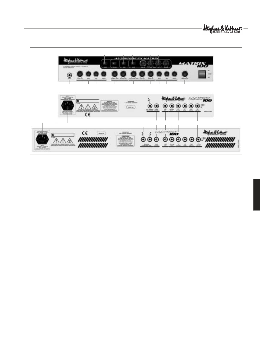
Overview of Control Features and
Connectors
1.1 Selecting channels and effect parameters
Use buttons 1 to 4 to select the MATRIX™ 100’s four channels,
CLEAN, CRUNCH, LEAD and WARP. These buttons correspond
to the buttons on the included footswitch. When the footswitch
is connected, buttons 1 to 4 serve display purposes only, and
the footswitch switches channels.
Use knobs 5 to 8 to adjust the effect for the given channel. The
FX MATRIX’s Autostore function automatically saves the edited
effect settings for every channel. You do not need to store
settings separately. Even if the amp is suddenly switched off or
power fails, the FX MATRIX™ will recall your settings.
1.2 Instrument inputs, channels and master volume
Connect your guitar to input 9. Please use high-quality shielded
cords only.
Use knobs 10 to 21 to shape the sound and determine the
volume of individual channels. You’ll fi nd a detailed description
of the channels in section 2. Knob 22 determines the amp’s
overall volume level. Always turn the MASTER knob all the way
down – that is, counterclockwise as far as it will go - before
powering your amp up.
Knobs 10 to 22 work in the same tried-and-true manner as
the controls on a classic amp. These settings are not stored.
This means that the actual position of the knob determines the
amp’s sounds.
1.3 Mains switch and mains socket
Use switch 23 to turn the MATRIX™ 100 on and off. Make a
habit of checking to make sure that the switch is set to the OFF
position before you connect the power cable to a mains power
supply. The MATRIX™ 100 ships with a separate power cord
that connects to socket 24. Please ensure that the mains
voltage matches the value indicated on the back panel of the
MATRIX™ 100. Get in touch with your Hughes & Kettner
®
dealer immediately if this is not the case or the included mains
cord’s plug does not fi t into the wall outlet.
1.4 Speaker out
Use jack or jack pair 25, EXTERNAL SPEAKER or SPEAKERS,
to connect speakers. All speakers are connected in parallel for
both the combo and the head.
MATRIX™ 100 COMBO
EXTERNAL SPEAKER: Connect cabinets with 8 ohms minimum
impedance to this jack. The impedance of connected speakers
must never be lower than 8 ohms!
MATRIX™ 100 HEAD
SPEAKERS: You can connect two cabinets to the head. The
minimum impedance is 4 ohms; ensure your rig’s impedance
never drops below 4 ohms! If you plug cabs into both jacks,
each cabinet’s impedance must be 8 ohms or higher. If you
24
25
26
27
28
29
30
31
9
10
20
19
18
17
16
15
14
1
12
11
23
22
21
13
2
3
4
5
6
7
8
MATRIX™100
Combo/Head
Front
MATRIX™100
Combo
Rear
MATRIX™100 Head Rear
32
9