Operating the nailer, Operational modes, Modos de operación – Husky HDN21901 User Manual
Page 4
Operating The Nailer
(Continued)
NO-MAR DECKING TIP
The no-mar decking tip is designed to
eliminate marks caused by the serrated
work contact element (WCE). The no-
mar tip may be removed if not
required (See REMOVING NO-MAR
DECKING TIP). Use tool in single cycle
mode (SEE OPERATIONAL MODES)
when no-mar tip is in place.
REMOVING NO-MAR DECKING TIP
1. Disconnect air
supply from
nailer.
2. Remove all fasteners from
magazine (See UNLOADING THE
NAILER).
3. Remove no-mar tip retaining ring.
4. Pry no-
mar tip
away
from the
work
contact
element.
5. Replace
retaining
ring onto
no-mar
tip, then
store tip
in safe
place for future use.
INSTALLING NO-MAR DECKING TIP
1. Disconnect air
supply from
nailer.
2. Remove all fasteners from
magazine (See UNLOADING THE
NAILER).
Since the tool can only be actuated by
first removing the finger from the
trigger, this is considered to be a more
restrictive mode of operation, suitable
for less experienced users.
BOTTOM TRIP MODE
When the red trigger is installed, the
nailer is in bottom trip mode. This
method is recommended when less
precise nail placement is required.
Operation in this mode requires trigger
to be depressed with nailer off of the
work surface. Then, the nose of the
nailer is tapped against the work
surface causing a nail to be driven.
Each time the Work Contact Element is
depressed, a nail is driven into the
work surface. Extreme care should be
taken because a nail will be driven
when the WCE is pressed against any
surface.
Since the tool can be actuated without
removing the finger from the trigger,
this is considered to be a less restrictive
mode, suitable for more experienced
users.
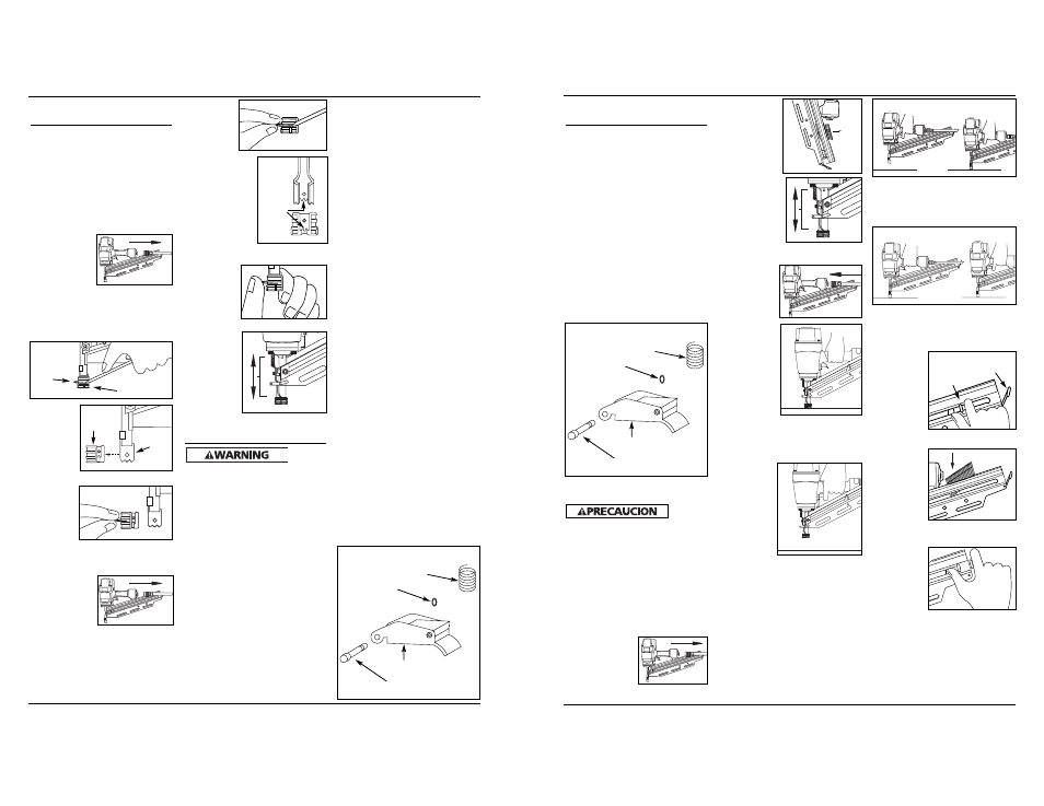
MODE CONVERSION
To convert the tool from one mode to
the other:
1. Remove o-ring on the side of
trigger pin.
2. Remove trigger pin, trigger, and
trigger spring.
3. Switch out only the trigger.
4. Replace trigger spring, trigger,
trigger pin, and o-ring.
Do not attempt to modify the trigger
components in any manner and do not
attempt to use any other trigger
components other than those intended
for this tool.
Contact a Customer Service
Representative at 1-800-543-6400 if you
have any questions.
3. Remove
retaining
ring from
no-mar tip.
4. Carefully place
no-mar tip over
the end of work
contact
element.
Position tip
onto WCE
making certain
serrated gooves
on each piece
are in line and fit snugly together.
5. Position
retaining
ring on
no-mar tip
and press
firmly in
place.
6. Check that
the WCE
and trigger
move up
and down
freely
without
sticking or
binding.
Operational Modes
Always
know the
operational mode of the nailer before
using. Failure to know the operational
mode could result in death or serious
personal injury.
This stick framing nailer may be
operated in the “Single Cycle” or the
“Bottom Trip” mode. The nailer is
delivered in the single cycle mode. A
separate ‘red’ trigger for “Bottom
Trip” mode is included with tool as an
accessory.
SINGLE CYCLE MODE
When the black trigger is installed,
nailer is in single cycle mode. This
method is recommended when precise
nail placement is required. Operation
in this mode requires trigger to be
pulled each time a nail is driven. Nailer
can be actuated by depressing the
Work Contact Element (WCE) against
work surface followed by pulling the
trigger.
The trigger must be released after each
fastener is driven to allow tool to reset.
4
Modos de Operación
(Continuación)
CONVERSIÓN DE MODO
Para convertir la herramienta de un
modo al otro:
1. Retire el anillo en O que se
encuentra a un lado del pasador del
gatillo.
2. Retire el pasador del gatillo, el
gatillo y el resorte del gatillo.
3. Cambie sólo el gatillo.
4. Vuelva a colocar el resorte del
gatillo, el gatillo, el pasador del
gatillo y el anillo en O.
No intente modificar los componentes
de gatillo de modo alguno, ni intente
usar ningún otro componente de
gatillo que no sean los diseñados para
esta herramienta.
Póngase en contacto con su
representante si tiene alguna
pregunta. Sírvase llamar 1-800-543-6400.
ELEMENTO DE CONTACTO
DE TRABAJO (WCE)
Verifique
el
funcionamiento del mecanismo de
disparo del elemento de contacto de
trabajo (WCE) antes de cada uso. El
WCE deberá moverse libremente sin
atracarse en ningún punto de toda su
distancia de desplazamiento. El resorte
del WCE deberá regresar al WCE a su
posición completamente extendida
luego de haberlo presionado. No ponga
en funcionamiento la clavadora si el
mecanismo de disparo del WCE no está
operando correctamente. Puede
ocasionar lesiones personales.
1. Desconecte el
abastecimiento
de aire de la
clavadora.
2. Retire todos
los clavos del
cargador (ver
Cómo
descargar la
clavadora).
3. Asegúrese de
que el gatillo
y el elemento
de contacto
de trabajo
(WCE) se
muevan
fácilmente
hacia arriba y hacia abajo sin
pegarse o atracarse.
4. Reconectar
el abaste-
cimiento de
aire a la
clavadora.
5. Presione el
elemento de
contacto de
trabajo
(WCE) contra
la superficie
de trabajo
sin tirar del
gatillo. La
clavadora
NO DEBE
FUNCIONAR.
No utilice la herramienta si ésta
funciona sin haber tirado del
gatillo. Puede causar lesiones
personales.
6. Retire la
clavadora
de la
superficie
de trabajo.
El elemento
de contacto
de trabajo
(WCE) debe
regresar a
su posición
inferior
original. Tire del gatillo. La
clavadora NO DEBE FUNCIONAR.
No utilice la herramienta si ésta
funciona cuando se levanta de la
superficie de trabajo. Puede causar
lesiones personales.
7. Tire del gatillo y presione el
elemento de contacto de trabajo
(WCE) contra la superficie de
trabajo. La clavadora DEBE
FUNCIONAR.
8. Presione el elemento de contacto
de trabajo (WCE) contra la
superficie de trabajo. Tire del
gatillo. La clavadora DEBE
FUNCIONAR.
CÓMO CARGAR LA CLAVADORA
1. Siempre conecte la herramienta al
abastecimiento de aire antes de
cargar los sujetadores.
2. Jale el
mecanismo
del
empujador
de clavos
hasta que
éste
engrane
con el
enganche
del cargador.
3. Cargue la
tira de
sujetadores
en la
ranura del
cargador.
Asegúrese
de que los
clavos
estén colocados en la herramienta
en la orientación correcta.
4. Presione el
empujador
con el
enganche
para desen-
ganchar al
empujador.
Asegúrese
de que la cabeza del último clavo
esté debajo de la cabeza del
empujador.
Grooves
1
2
Mode Conversion
Trigger spring
O-ring
Trigger pin
Trigger
1
2
Retaining
Ring
No-Mar Tip
Work
Contact
Element
No-
Mar
Tip
Operating Instructions
Modelo HDN21901
Conversión De Modo
el resorte del gatillo
Anillo en O
el pasador del gatillo
el gatillo
21 Sp
El mecanismo
del
empujador
de clavos
El
enganche