Quick start — dvs 406, Installation, Step 1 – Extron Electronics DVS 406 Series User Manual
Page 3: Step 2, Step 3, Step 4, Step 5, Step 6, Qs-1 dvs 406 • quick start, Rear panel video inputs
QS-1
DVS 406 • Quick Start
Quick Start — DVS 406
Installation
Step 1
Turn off power to the scaler and input and output
devices, and remove power cords from them.
Step 2
Install the four rubber feet on the bottom of the
DVS 406 scaler, or mount the scaler in a rack.
Step 3
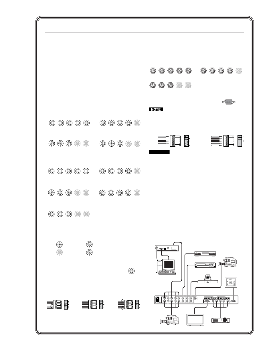
Attach input devices to the scaler.
Rear panel video inputs
Input 1: RGB and HD YUV pass-through
Input 2: RGB pass-through, RGBcS,YUVi, YUVp
Inputs 3 - 5: composite video, S-video
Input 6: SDI (serial digital interface)
Attach an SDI source to this BNC
(DVS 406 D and DVS 406 AD models only).
Rear panel audio inputs
Inputs 1 - 6: balanced and unbalanced
Step 4
Attach output devices to the scaler.
Rear panel video output
Output BNC connectors
Output 15-pin HD connector
Both connectors will output simultaneously.
The sync format is the same for both outputs.
Rear panel audio output
CAUTION
Connect the sleeve to ground.
Connecting the sleeve to a negative (-)
terminal will damage the audio output
circuits.
Step 5
Plug the DVS 406, and input and output devices
into a grounded AC source, and turn on the input
and output devices.
Step 6
Use the LCD menu screens (see the next page) or
RS-232 programming to configure the scaler. See
chapter two for installation and operation
procedures, and see chapter three for
programming information.
RGsB
input
HDTV Component (YUV)
video input
RGBHV
input
RGBS
input
HD YUV to / RGB PASS THROUGH
R
G
B
V
H
HD YUV to / RGB PASS THROUGH
R
G
B
H
HD YUV to / RGB PASS THROUGH
R
G
B
V
H
HD YUV to / RGB PASS THROUGH
R
G
B
V
H
V
/HV
/HV
/R-Y
/Y
/B-Y
/HV
/R-Y
/Y
/B-Y
/R-Y
/Y
/B-Y
/HV
/R-Y
/Y
/B-Y
Component
video input
(R-Y, Y, B-Y)
RGBHV
input
RGBS
input
R
G
B
V
H
/HV
2 - RGB PASS THROUGH / R-Y, B-Y, Y
/R-Y
/Y
/B-Y
R
G
B
V
H
/HV
/R-Y
/Y
/B-Y
R
G
B
V
H
/HV
/R-Y
/Y
/B-Y
2 - RGB PASS THROUGH / R-Y, B-Y, Y
2 - RGB PASS THROUGH / R-Y, B-Y, Y
RGsB
input
R
G
B
H
/HV
V
/R-Y
/Y
/B-Y
2 - RGB PASS THROUGH / R-Y, B-Y, Y
RGBcS
input
2 - RGB PASS THROUGH / R-Y, B-Y, Y
R
G
B
V
H
/HV
/R-Y
/Y
/B-Y
S-video
input
Y
/VID
C
Composite video
input
C
Y
/VID
SDI
LR
A
UDIO
LR
A
UDIO
LR
A
UDIO
Unbalanced Input
Tip
Sleeve
Tip
Sleeve
Balanced Input
Tip
Ring
Sleeve (s)
Tip
Ring
Tip
Ring
Sleeve (s)
Tip
Ring
Balanced Input
(high impedance)
(high impedance)
(600 ohms)
600 ohms
600 ohms
RGBS
RGBHV
RGsB (Sync on Green)
RsGsBs
(output only if input is RsGsBs)
R
G
B
H/HV
V
R
G
B
H/HV
V
R
G
B
H/HV
V
Unbalanced Output
Tip
See Caution
Sleeve (s)
Tip
See Caution
Balanced Output
Tip
Ring
Sleeve (s)
Tip
Ring
LR
A
UDIO
A
UDIO
LR
2A MAX
100-240V 50-60Hz
RS-232
RGB
2 - RGB PASS THROUGH / R-Y, B-Y, Y
1 - RGB PASS THROUGH
SDI
5
6
4
3
R
G
B
H/HV
V
R
/RY
G
/Y
B
/B-Y
R
G
B
V
V
C
H
/HV
Y
/VID
C
Y
/VID
C
Y
/VID
H
/HV
O
U
T
I
N
T
P
U
T
S
1
L
R
INPUTS
OUTPUT
2
L
R
3
L
R
4
L
R
L
R
5
L
R
6
L
R
DVS 406
RGB 109
xi
RS-232
Control
DVD Player
Codec
VCR
Projector
Plasma Display
Video Camera 1
Video Camera 2
RGB 109xi
BUFFERED LOCAL
MONITOR OUTPUT
H. SHIFT
INPUT
VGA INTERFACE W/ADSP
ID PIN 4
ID PIN 11
PC Computer
Application Example
RGB