Installation and operation, cont’d, Caution – Extron Electronics DVS 406 Series User Manual
Page 18
Installation and Operation, cont’d
DVS 406 • Installation and Operation
2-6
9
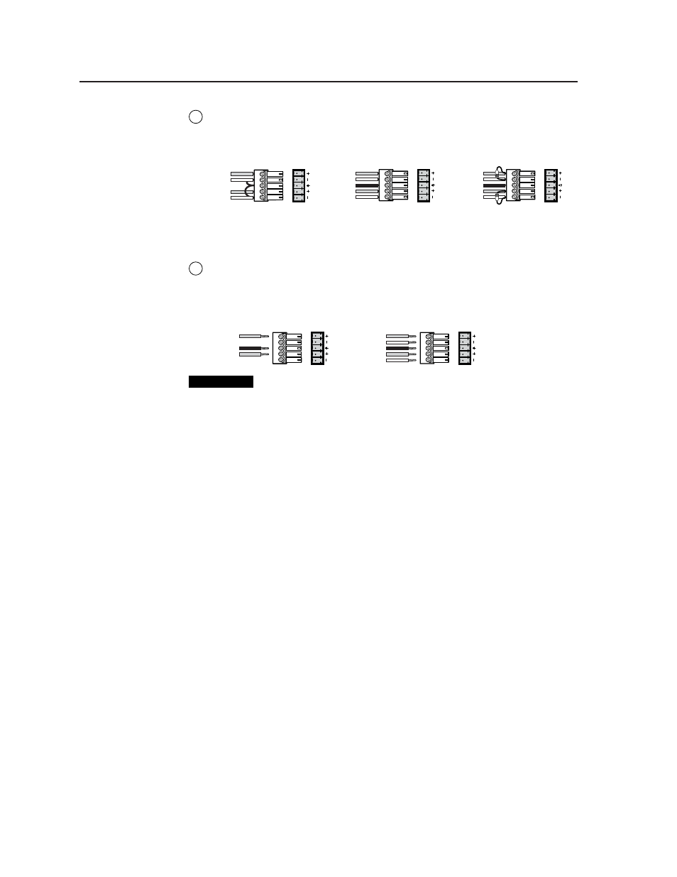
Audio inputs 1 through 6
— Each input has a 3.5 mm, 5-pole captive screw
connector for balanced or unbalanced stereo audio input. See the following
wiring diagrams to wire a connector for the appropriate input type and
impedance level. High impedance is generally over 800 ohms.
LR
A
UDIO
LR
A
UDIO
LR
A
UDIO
Unbalanced Input
Tip
Sleeve
Tip
Sleeve
Balanced Input
Tip
Ring
Sleeve (s)
Tip
Ring
Tip
Ring
Sleeve (s)
Tip
Ring
Balanced Input
(high impedance)
(high impedance)
(600 ohms)
600 ohms
600 ohms
Captive screw connector wiring for rear panel audio inputs
10
Line level audio output
— For unamplified audio output, connect an
audio device, such as an audio recorder, VCR, or powered speakers, to this
3.5 mm, 5-pole captive screw connector. Follow the diagram below for
correct wiring.
Unbalanced Output
Tip
See Caution
Sleeve (s)
Tip
See Caution
Balanced Output
Tip
Ring
Sleeve (s)
Tip
Ring
LR
A
UDIO
A
UDIO
LR
CAUTION
Connect the sleeve to ground. Connecting the sleeve to a
negative (-) terminal will damage the audio output circuits.
The gain can be set separately for each input channel so that there is no
audible difference in level when switching between inputs. See the section
“Audio Configuration”, in this chapter, for information on adjusting the
audio output level via LCD menu and front panel controls. See chapter
three, “Serial Communication”, for information on using the Simple
Instruction Set (SIS) commands and the Windows-based control program to
adjust audio levels and to set audio breakaway.