1 program counter block, 2 flags – Epson 6200A User Manual
Page 10
4
EPSON
S1C6200/6200A CORE CPU MANUAL
2 MEMORY AND OPERATIONS
2.1.1 Program counter block
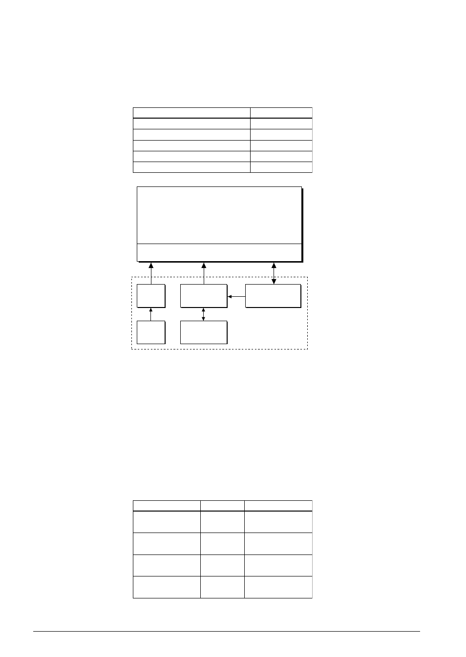
The program counter is used to point to the next instruction step to be executed by the CPU. See Figure
2.1.1.1.
The program counter has the following registers.
Table 2.1.1.1 Program counter registers
PCB (Program Counter-Bank)
PCP (Program Counter-Page)
PCS (Program Counter-Step)
NBP (New Bank Pointer)
NPP (New Page Pointer)
Register
Size
1-bit register
4-bit counter
8-bit counter
1-bit register
4-bit register
Program memory
(8,192 12-bit words max.)
Program counter block
Address decoder
PCB
(1)
NBP
(1)
PCP
(4)
NPP
(4)
PCS
(8)
Fig. 2.1.1.1 Program counter configuration
PCB, PCP and PCS together from a 13-bit counter which can address any location in program memory.
PCP and PCS together from a 12-bit counter which can address any location within a given bank of pro-
gram memory. Each time an instruction other than a jump is executed, this counter increments by one.
Thus, a jump instruction does not need to be executed between the last step of one page and the first step of
the next.
The contents of NBP and NPP are loaded into PCB and PCP each time an instruction is executed. On reset,
NBP and NPP are loaded with the same values as PCB and PCP.
2.1.2 Flags
The following flags are provided.
Table 2.1.2.1 Flags
Interrupt
Decimal mode
Zero
Carry
Flag
Size
1: Enabled
0: Disabled
1: Decimal
0: Hexadecimal
1: Set
0: Ignored
1: Set
0: Ignored
Menus
I
D
Z
C