Connecting the twisted pair segment, Receive (rx) transmit (tx) – Enterasys Networks 2H252-25R User Manual
Page 36
Connecting to the Network
3-10
Installation
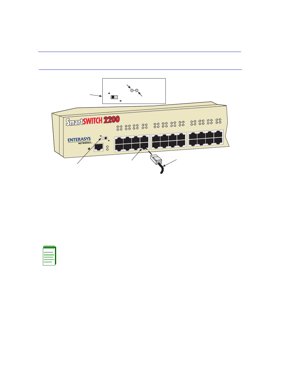
Figure 3-6
Connecting the Twisted Pair Segment
3. Verify that a link exists by checking that the port RX LED is on (flashing amber, blinking green,
or solid green). If the RX LED is off and the TX LED is not blinking amber, perform the
following steps until it is on:
a. Verify that the LED switch located near the COM port of the device is in the left-most
position (RX and TX LED indicators).
b. Verify that the UTP cabling used is Category 3 (for 10BASE-T) or Category 5 (for
10BASE-T or 100BASE-TX). The Category 5 cabling must have an impedance of between
85 and 111 ohms.
c. Verify that the 100BASE-TX device at the other end of the twisted pair segment is powered
up.
d. Verify that the RJ45 connector on the twisted pair segment has the proper pinouts.
Depending on what device is connected to the 2H252-25R, a straight-through or crossover
cable may be used.
shows the wiring for both types of cables.
e. Check the cable for continuity.
NOTE: If a port is to operate at 10 and 100 Mbps, Category 5 cabling must be used.
Refer to
for information about 100BASE-TX networks and cabling.
Receive (RX)
Transmit (TX)
LED
MODE
RX-TX
DPX-SPD
4005_00_07
RESET
COM
PWR
CPU
2H252-25R
2X 4X 6X 8X 10X 12X 14X 16X 18X 20X 22X
24X
FAST ETHERNET WORKGROUP
SWITCH
1
2
3
4
5
6
7
8
9
10
15
16
21
22
23
24
11
12
19
20
17
18
13
14
LED
MODE
RX-TX
DPX-SPD
Twisted Pair Cable
Port
LED MODE Switch
in RXTX position
LED MODE Switch