Connecting high-speed stacking cables, Connecting high-speed stacking cables -10, Attaching the rackmount brackets -10 – Enterasys Networks Enterasys SecureStack B2 B2G124-24 User Manual
Page 40: Fastening the switch to the rack -10, Connecting high‐speed stacking cables, Connecting high‐speed, Stacking cables, Ба б а
Connecting High-Speed Stacking Cables
3-10 Hardware Installation
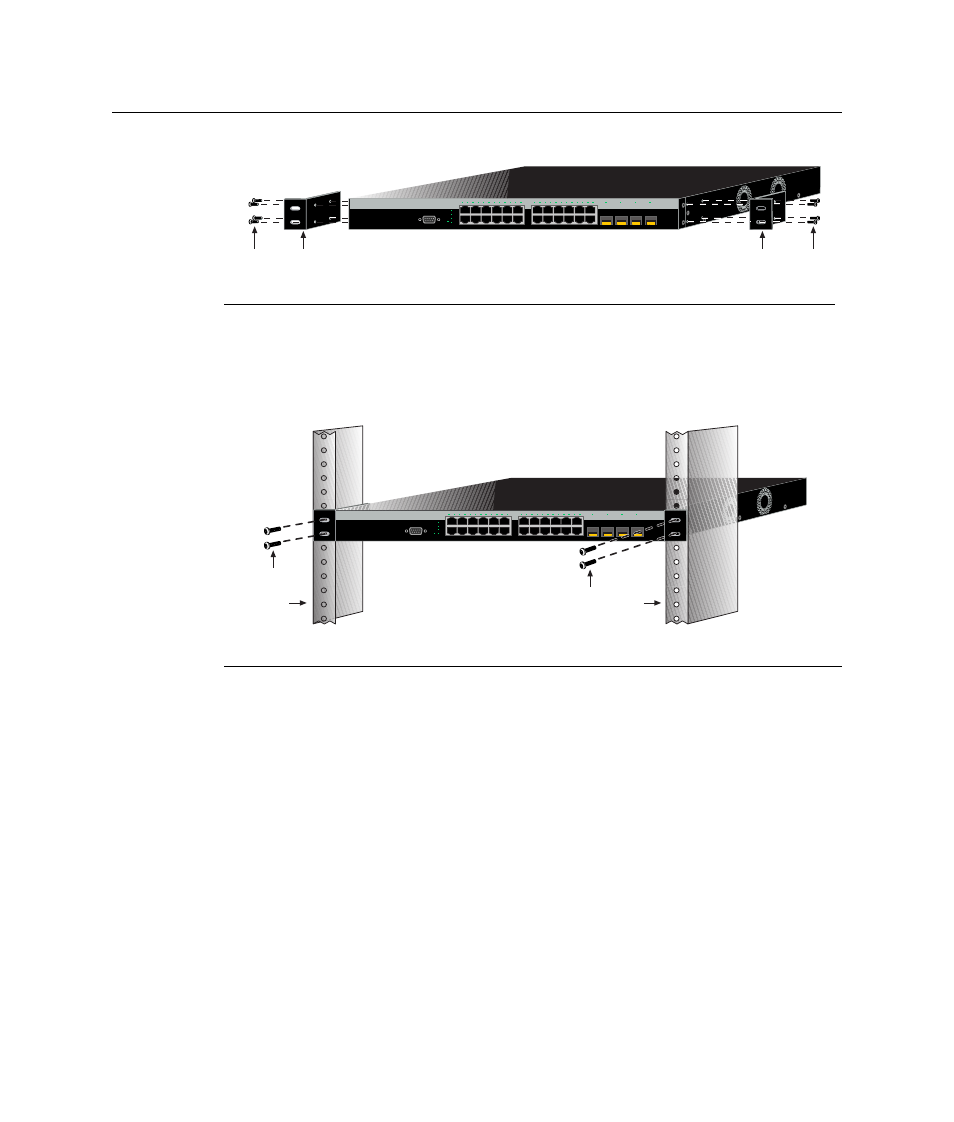
Figure 3-5 Attaching the Rackmount Brackets
2.
With the mounting brackets attached, position the switch between the vertical frame
members of the 19‐inch rack as shown in
. Then fasten the switch securely
to the frame using four mounting screws (user supplied).
Figure 3-6 Fastening the Switch to the Rack
3.
If you are installing this switch in a stacked configuration, repeat this procedure for
each switch until all switches have been installed in the stack, then proceed to
“
Connecting High‐Speed Stacking Cables
” on page 3‐10. Otherwise, proceed to
Connecting AC and RPS‐SYS Power
Connecting High-Speed Stacking Cables
The stack of switches can be connected in a ring or daisy chain topology. In a ring
topology all the switches are connected. The only difference in the cable connections in a
daisy chain topology is that one cable is not installed. Up to seven or eight switches can be
stacked together and connected by high‐speed stacking cables. You can add switches and
reach up to a maximum of 384 Ethernet ports per stack. The high‐speed stacking cables
allow the entire stack to operate with a single IP address.
1 Rackmount brackets
2 M3x6 mm flathead screws
1 Rails of 19-inch rack
2 Mounting screws (supplied by user)
C2G124-24
Б
А
Б
А
Console
1
2
23
24
21
22
23
24
CPU
UP
RPS
MGR
DOWN
1
2
3
4
5
6
7
8
9
10
11
12
13
14
15
16
17
18
19
20
21
22
23
24
11
12
13
14
21
22
23
24
B2G124-24
Б
А
Б
А
Console
1
2
23
24
21
22
23
24
CPU
UP
RPS
MGR
DOWN
1
2
3
4
5
6
7
8
9
10
11
12
13
14
15
16
17
18
19
20
21
22
23
24
11
12
13
14
21
22
23
24
B2G124-24