Blower motor systems installation – Electrolux Hood Insert EI48HI55KS User Manual
Page 11
11
joints. Use furnace duct tape to seal all joints
tightly.
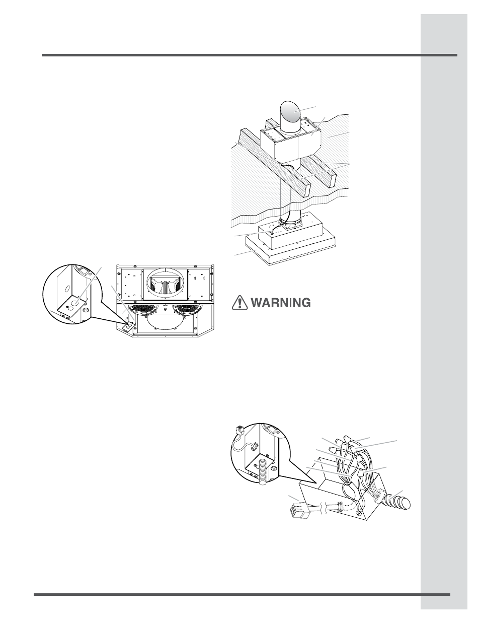
Make Electrical Connections for Remote Blower
Motor System
Electrical Shock Hazard
Disconnect power before servicing.
Replace all parts and panels before operating.
Failure to do so can result in death or electrical
shock.
Electrical Connection Inside Remote Blower System
Disconnect power.
Connect the wires from the wiring conduit to the
wires from the motor electrical plug cable inside
the remote blower housing terminal box.
1.
2.
E. Red wires
F. Blue wires
G. Gray wires
H. Green (or yellow/green) and
green/yellow wires
I.Motor electrical plug cable
A.UL listed or CSA approved
1
⁄
2
” (1.3 cm) wiring conduit
B.UL listed wire connectors
C.Black wires
D.White wires
previously removed. If it is removed, reattach the
motor electrical plug to the connector on the
blower motor assembly.
Complete Preparation
Determine and make all necessary cuts for the
vent system.
IMPORTANT: When cutting or drilling into the ceiling
or wall, do not damage electrical wiring or other hid-
den utilities.
Determine the location where the ½” (1.3 cm)
wiring conduit will be routed through the ceiling or
wall between the remote blower and the hood insert.
Drill a 1¹⁄
4
” (3.2 cm) hole at this location.
Locate the electrical terminal boxes in the remote
blower housing and hood insert (see “Complete
Preparation” in the “Prepare Location” section).
Remove the terminal box covers and set the
covers and screws aside.
Remove the electrical knockout from the remote
blower housing and hood insert (see “Preparation”
in the “Prepare Location” section) to prepare for
the installation of the UL listed or CSA approved
½” (1.3 cm) wiring conduit and conduit connector.
NOTE: Strain relief conduit are supplied with
remote blower hardware.
With the hood insert mounted (see the “Install Hood
Insert” section), run the ½” (1.3 cm) wiring conduit
between the remote blower motor housing and the
hood insert. Pull enough ½” (1.3 cm) wiring conduit
to allow for easy connection to the terminal boxes
in the remote blower housing and hood insert.
Run the six 18 AWG wires through the
1
⁄
2
” (1.3
cm) wiring conduit and conduit connectors and
into the terminal boxes on the remote blower
housing and hood insert. Leave enough wire length
in each terminal box to make the wiring connections.
Install the conduit connectors and conduit to the
remote blower housing and hood insert electrical
terminal boxes.
NOTE: Strain relief conduit are supplied with
remote blower hardware.
Connect the vent system to the hood insert and
remote blower motor system. Use clamps at all
1.
2.
3.
4.
5.
6.
7.
8.
9.
A. Electrical terminal box
B. Electrical knockout
Blower Motor Systems Installation
B
A
A
B
C
D
E
F
G
A. Vent System
B. Remote Blower Motor
C. Ceiling
D. Roof rafters / Plywood
E. Remote Blower Wiring
Conduit
F. Hood Insert Wiring
Conduit
G. Hood Insert
A
B
C
D
E
F
G
H
I