ProSoft Technology 5201-DFNT-DH485 User Manual
Page 35
Reference DH485
♦ ProLinx Gateway
Driver Manual
DH485 Interface
ProSoft Technology, Inc.
Page 35 of 44
August 27, 2009
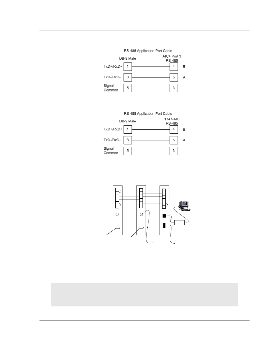
When connecting to port 3 of an AIC+ module, the following is the correct wiring:
When connecting to a 1747-AIC module, the following is the correct wiring:
The following illustration shows an example DH-485 network.
1
2
3
4
5
6
Chassis Gnd
Shield
Common
B
A
Termination
AIC+
1
2
3
4
5
6
AIC+
1
2
3
4
5
6
1747
-
AIC
To SLC 5/03
Channel 1
Port 2
Port 1
To
MicroLogix
1000
To
ProSoft DH485
RS-232
Workstation
To
ProSoft DH485
RS-232
DH485
Port RS-485
DB-9 Male
1747-PIC
This network displays the two different methods to configure the module for a
DH-485 network. Please note there is no place on the module’s RS-485 to land
the shield, and when used in the configuration shown, it must be wired externally.
Verify that the RS interface jumper on the module is set to the correct position:
RS-232 or RS-485.
Note: Terminating resistors are generally not required on the RS-485 network, unless you are
experiencing communication problems that can be attributed to signal echoes or reflections. In this
case, install a 120 ohm terminating resistor on the RS-485 line.