ProSoft Technology ILX34-MBS485 User Manual
Page 28
Configuration
Page 28 of 34
ProSoft Technology, Inc.
February 18, 2015
3.6
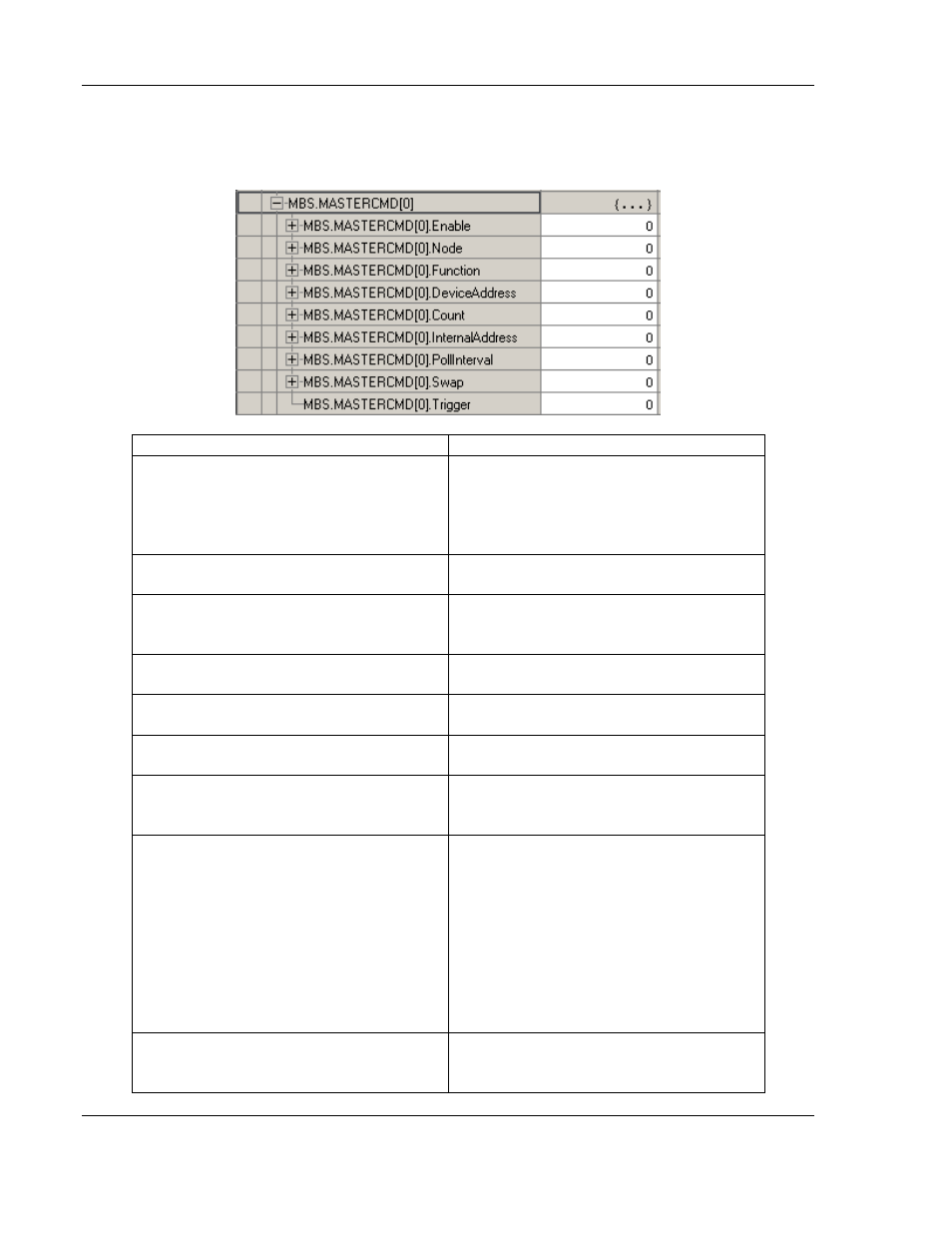
Master Command Structure
Label
Description
Enable
0=Disable
1=Enable the Command: Polling and
Trigger allowed.
2=Enable the Command: Only Trigger
allowed.
Node
Node address of the target device on
the network (1-255).
Function
Function code for the command. 1, 2,
3, 4, 5, 6, 15 and 16 allowed for Master
and Slave. 8 allowed for Slave only.
DeviceAddress
Address in remote device associated
with the command (0-65535).
Count
Number of points associated with the
command.
InternalAddress
PLC Tag Internal address associated
with the command.
PollInterval
Minimum number of milliseconds
between issuance of command (0-2,
147, 483, 647ms).
Swap
0=None. No change is made in byte
ordering.
1=Words
– The words are swapped.
2=Words & Bytes
– The words are
swapped, and then the bytes in each
word are swapped.
3=Bytes
– The bytes in each word are
swapped.
The words should be swapped only
when using an even number of words.
Trigger
1=Trigger the message. Can be
triggered anytime the command is
enabled.