ProSoft Technology MVI71-GSC User Manual
Page 49
Reference MVI71-GSC
♦ PLC Platform
Generic Serial Communication Module
ProSoft Technology, Inc.
Page 49 of 82
January 31, 2008
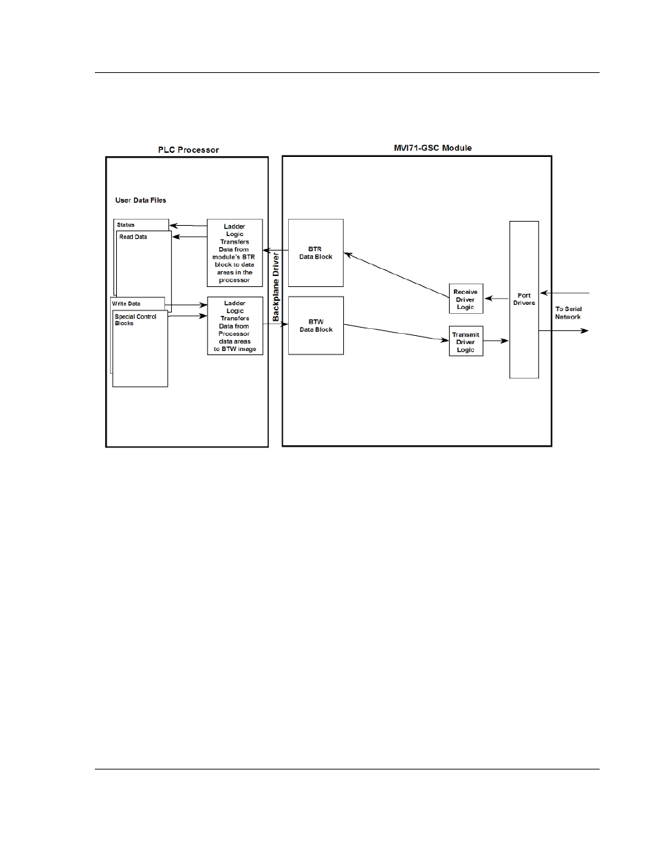
The following illustration shows the data transfer method used to move data
between the PLC processor, the MVI71-GSC module and the serial devices
when the BTR/BTW interface is utilized:
As shown in the diagram above, all data transferred between the module and the
processor over the backplane is through the BTR/BTW images. Ladder logic
must be written in the PLC processor to interface the BTR and BTW blocks of
data with data defined in the user defined files. The user is responsible for
handling and interpreting all data received on the application ports and
transferred to the processor. Additionally, the user is responsible for constructing
messages to be transferred out of the application ports by building the messages
in the BTW blocks sent to the module.
When the side-connect interface is utilized, data is transferred directly from the
module to the user data files. Block identification codes are used as the first word
of each of these files to coordinate data movement between the module and the
PLC processor. When the first word of each file is set the same, the module has
control of the read and write files. Any data contained in the write file will be
transferred to the appropriate application port. The module will place any newly
received or buffered data in the read file. When the module has finished
operating on the files, it will set the first word in the read file to a value different
than the write file. This signals to the PLC that it has control of the two files. The
PLC should handle any newly received read data and place any data to transmit
in the write file. After completing these tasks, the ladder logic should set the first
word in the write file to match the value in the read file. The data flow diagram for
the side-connect interface is shown below: