ProSoft Technology MVI69-DFCM User Manual
Page 67
Reference MVI69-DFCM
♦ CompactLogix or MicroLogix Platform
DF1 Interface Module
ProSoft Technology, Inc.
Page 67 of 117
November 3, 2008
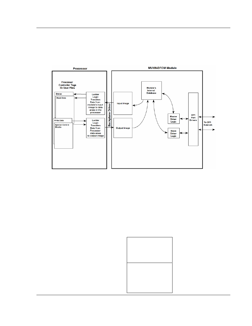
The processor inserts data to the module's output image to transfer to the
module. The module's program extracts the data and places it in the module's
internal database. The output image for the module may be set to 61, 121, or 241
words depending on the block transfer size parameter set in the configuration
file.
The following illustration shows the data transfer method used to move data
between the CompactLogix or MicroLogix processor, the MVI69-DFCM module
and the DFCM network.
All data transferred between the module and the processor over the backplane is
through the input and output images. Ladder logic must be written in the
CompactLogix or MicroLogix processor to interface the input and output image
data with data defined in the Controller Tags. All data used by the module is
stored in its internal database. The following illustration shows the layout of the
database:
Module's Internal Database Structure
5000 registers for user data
0
Register Data
4999
3000 words of configuration and
status data
5000
Status and Config
7999