ProSoft Technology MVI69-DNPSNET User Manual
Page 83
Reference MVI69-DNPSNET
♦ CompactLogix or MicroLogix Platform
Distributed Network Protocol Interface Module
ProSoft Technology, Inc.
Page 83 of 119
November 3, 2008
Note that in one block, one or more data types may be transferred. This is
especially important when considering the counter and Float data. They require
two registers to store their value. The value of a counter should never be passed
in two separate blocks. To avoid this potential problem, always configure the
module to have the counter data start on an even word number same rule
applies to Float points.
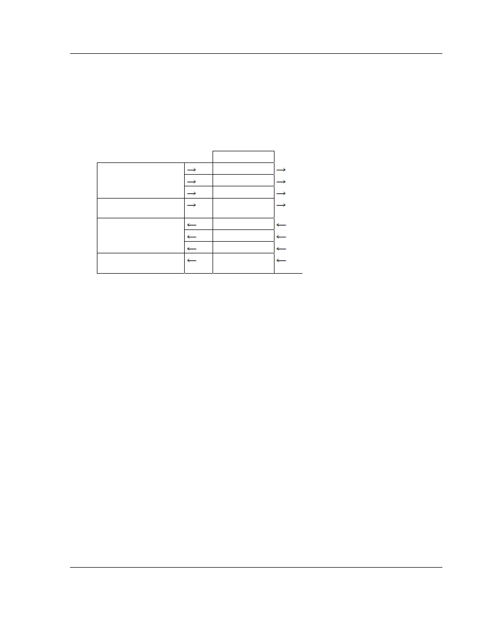
The following figure displays the direction of movement of the DNP database
data between the module and the processor.
DNP
MEMORY
DIGITAL INPUT DATA
ANALOG INPUT DATA
WRITE BLOCK FROM
PROCESSOR
FLOAT INPUT DATA
WRITE BLOCK FROM
PROCESSOR
COUNTER DATA
BINARY OUTPUT DATA
ANALOG OUTPUT DATA
READ BLOCK FROM
MODULE
FLOAT OUTPUT DATA
READ BLOCK FROM
MODULE
FROZEN COUNTER, LAST
VALUE AND EVENT DATA
It is important to understand the relationship of the block identifications and the
data in the module. Confident data handling in the module is only accomplished if
the user defines a consistent set of parameters in the module configuration,
handles the read and write operations for the blocks in the module in the PLC
ladder logic and understands the requirements of the DNP master unit.
The Reference chapter contains forms to aid in designing your system. They can
be used to document the relationship between the point assignments, block
identification numbers and the PLC file and offset values and to define the
program configuration. Use these forms during your design phase.