ProSoft Technology MVI69-DNPSNET User Manual
Page 68
MVI69-DNPSNET ♦ CompactLogix or MicroLogix Platform
Reference
Distributed Network Protocol Interface Module
Page 68 of 119
ProSoft Technology, Inc.
November 3, 2008
Data contained in this database is paged through the input and output images by
coordination of the CompactLogix or MicroLogix ladder logic and the MVI69-
DNPSNET module's program. Up to 248 words of data can be transferred from
the module to the processor at a time. Up to 247 words of data can be
transferred from the processor to the module.
Each block transferred from the module to the processor or from the processor to
the module contains a block identification code that describes the content of the
block.
The following table defines the blocks used by this module:
Block Number
Function/Description
0 or -1
Dummy Blocks: Used by module when no data is to be transferred
1 to 150
DNP Data blocks
1000 to 1149
Output initialization blocks
9250
Status Data Block
9958
PLC Binary Input Event data
9959
PLC Analog Input Event Data
9970
Set PLC time using module's DNP time
9971
Set module's time using PLC time
9998
Warm Boot Request from PLC (Block contains no data)
9999
Cold Boot Request from PLC (Block contains no data)
Blocks 1 to 150 transfer data between the module and the processor. Blocks
1000 to 1149 are utilized to transfer the initial output databases (binary and
analog output data) from the processor to the module at startup. Blocks 9958 to
9999 are used for command control of the module. Each group of blocks are
discussed in the following topics.
Normal Data Transfer
Normal data transfer includes the paging of the user data found in the module's
internal databases between the module and the controller. These data are
transferred through read (input image) and write (output image) blocks. Refer to
the Module Set Up section for a description of the data objects used with the
blocks and the ladder logic required. Each data block transferred between the
module and the processor has a specific block identification code that defines the
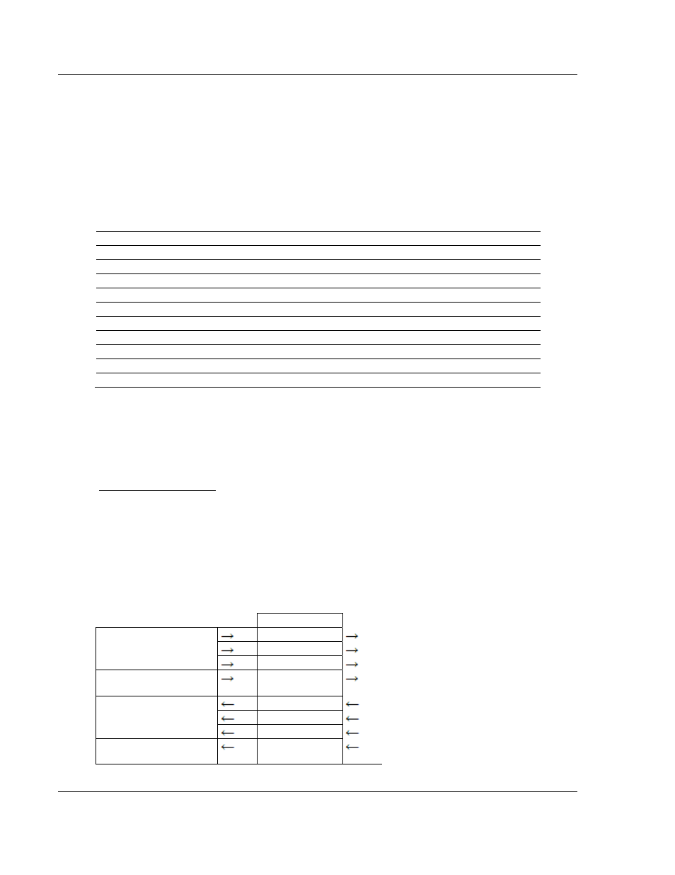
data set contained in the block. The following illustration shows the direction of
movement of the DNP data types between the module and the processor:
DNP
MEMORY
DIGITAL INPUT DATA
ANALOG INPUT DATA
WRITE BLOCK FROM
PROCESSOR
FLOAT INPUT DATA
WRITE BLOCK FROM
PROCESSOR
COUNTER DATA
BINARY OUTPUT DATA
ANALOG OUTPUT DATA
READ BLOCK FROM
MODULE
FLOAT OUTPUT DATA
READ BLOCK FROM
MODULE
FROZEN COUNTER, LAST
VALUE AND EVENT DATA
The structure and function of each block is described in the following topics: