6 wiring the power inputs, 7 wiring the fault alarm contact – PLANET IFT-802 User Manual
Page 10
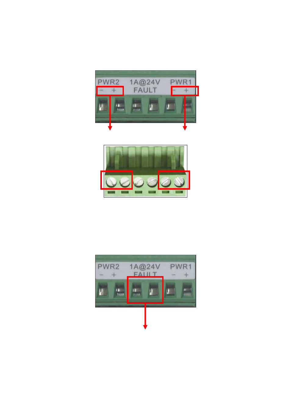
2.1.6 Wiring the Power Inputs
Please follow below steps to insert the power wire.
V - V + V - V +
1. Insert the positive and negative wires into the V+ and V- connector on the terminal block connector.
2. To tighten the wire-clamp screws for preventing the DC wires to loose.
2.1.7 Wiring the Fault Alarm Contact
The fault alarm contact is in the middle of terminal block connector as below figure shows. By inserting
the wires and set the DIPswitch at "ON" status, it will detect when power is failure or port link failure and
form an open circuit. And, the following figure shows an application example for the fault alarm contact.
Inset the wires into the falult alarm contact
Power Notice:
The wire range of terminal block is from 12~ 24 AWG.
- ISW-1022M (167 pages)
- ADE-2400A (8 pages)
- ADE-4400 (2 pages)
- ADE-3400 (2 pages)
- ADE-3400 (61 pages)
- ADE-3400 (73 pages)
- ADW-4401 (84 pages)
- ADE-4400 (2 pages)
- ADE-3100 (51 pages)
- ADE-3410 (2 pages)
- ADW-4401 (2 pages)
- ADW-4401 (2 pages)
- ADN-4000 (2 pages)
- ADN-4000 (118 pages)
- ADN-4000 (91 pages)
- ADN-4100 (115 pages)
- ADN-4100 (2 pages)
- ADN-4100 (2 pages)
- ADN-4100 (2 pages)
- ADN-4100 (104 pages)
- ADN-4102 (2 pages)
- ADU-2110A (2 pages)
- ADU-2110A (37 pages)
- ADW-4302 (8 pages)
- ADW-4302 (6 pages)
- ADW-4100 (57 pages)
- GRT-501 (52 pages)
- GRT-501 (51 pages)
- PRT-301W (32 pages)
- VC-100M (26 pages)
- CS-2000 (13 pages)
- CS-2000 (573 pages)
- CS-2000 (16 pages)
- BM-525 (205 pages)
- CS-1000 (226 pages)
- BM-2101 (278 pages)
- CS-2001 (16 pages)
- CS-2001 (848 pages)
- CS-500 (12 pages)
- CS-5800 (12 pages)
- SG-4800 (182 pages)
- FRT-401NS15 (12 pages)
- FRT-401NS15 (76 pages)
- FRT-405N (2 pages)
- FRT-405N (108 pages)