Rear panel features and cabling, Caution, Mvc 121 • installation and operation – Extron Electronics MVC 121 User Manual
Page 19
MVC 121 • Installation and Operation
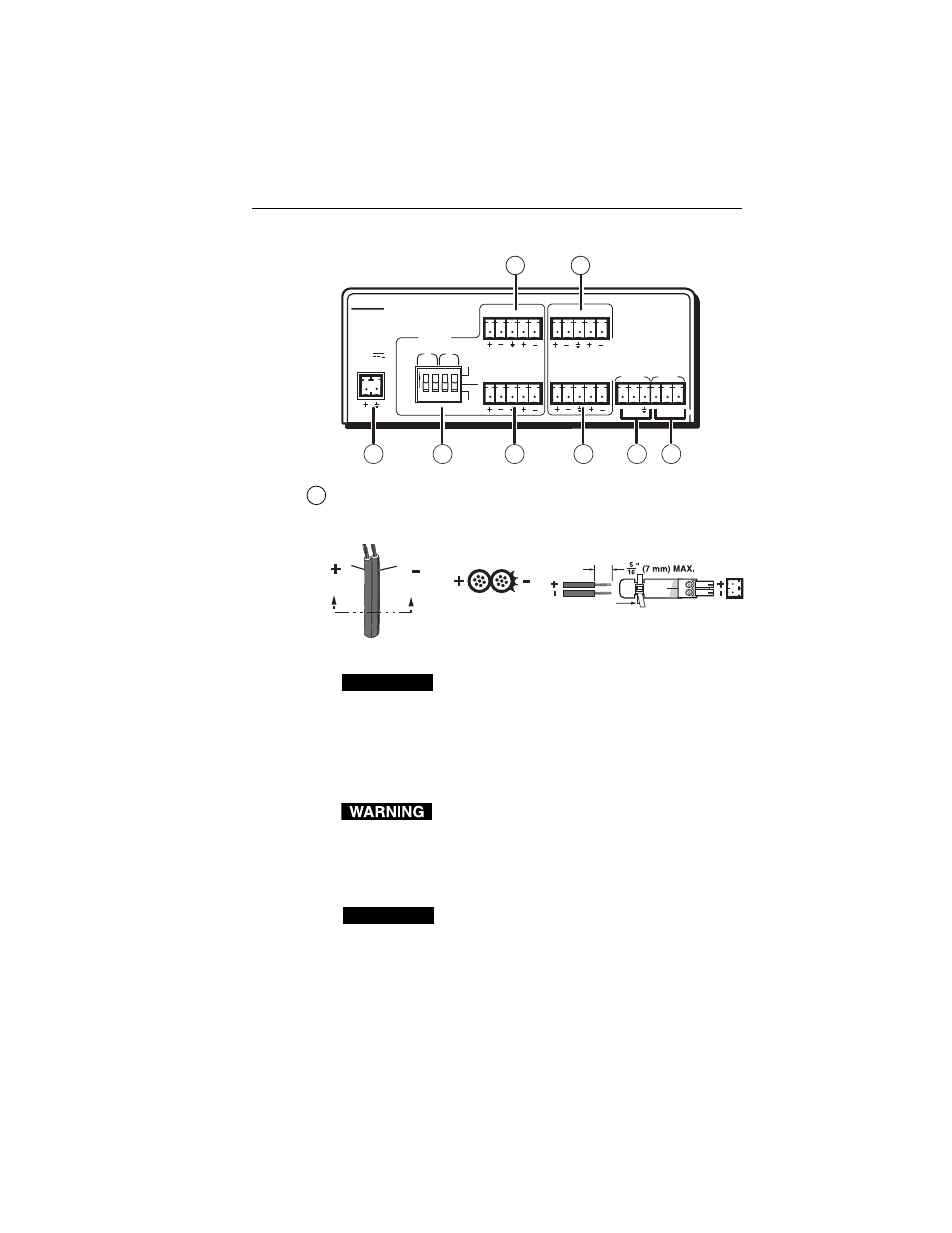
Rear Panel Features and Cabling
MVC 121
ON
INPUTS
OUTPUT
S
LEVEL
48V
ON
OFF
MAIN 3
LINE
MIC
RS-232
MUTE
Tx Rx
POWER
12V
0.5A MAX
L
1
2
R
3
1
2
3
4
1 2 1 2
MIXER/VOLUME
CONTROLLER
FIXED
L
R
MIC 1
MIC 2
VARIABLE
L
R
7
8
1
2
3
5
4
6
1
Power connector
— Connect the included 12 VDC external
power supply into the 2-pole 3.5 mm captive screw connector.
Be careful to observe the correct polarity.
Orange Captive Screw
Connector
Tie Wrap
Power Supply
Output Cord
Ridges
Smooth
A
A
SECTION A–A
CAUTION
When connecting the power supply, voltage
polarity is extremely important. Applying power
with incorrect voltage polarity could damage the
power supply and the MVC 121. Identify the
power cord negative (ground) lead by the ridges on
the side of the cord or a black heat shrink wrapping
around it.
The two power cord wires must be kept separate
while the power supply is plugged in. Remove
power before wiring.
To verify the polarity before connection, check the no load
power supply output with a voltmeter.
CAUTION
The length of the exposed (stripped) copper wires is
important. The ideal length is 5/16” (7 mm).
Longer bare wires can short together. Shorter
wires are not as secure in the direct insertion
connectors and could be pulled out.
2-7