Avago Technologies HEDS-8949 User Manual
Page 3
3
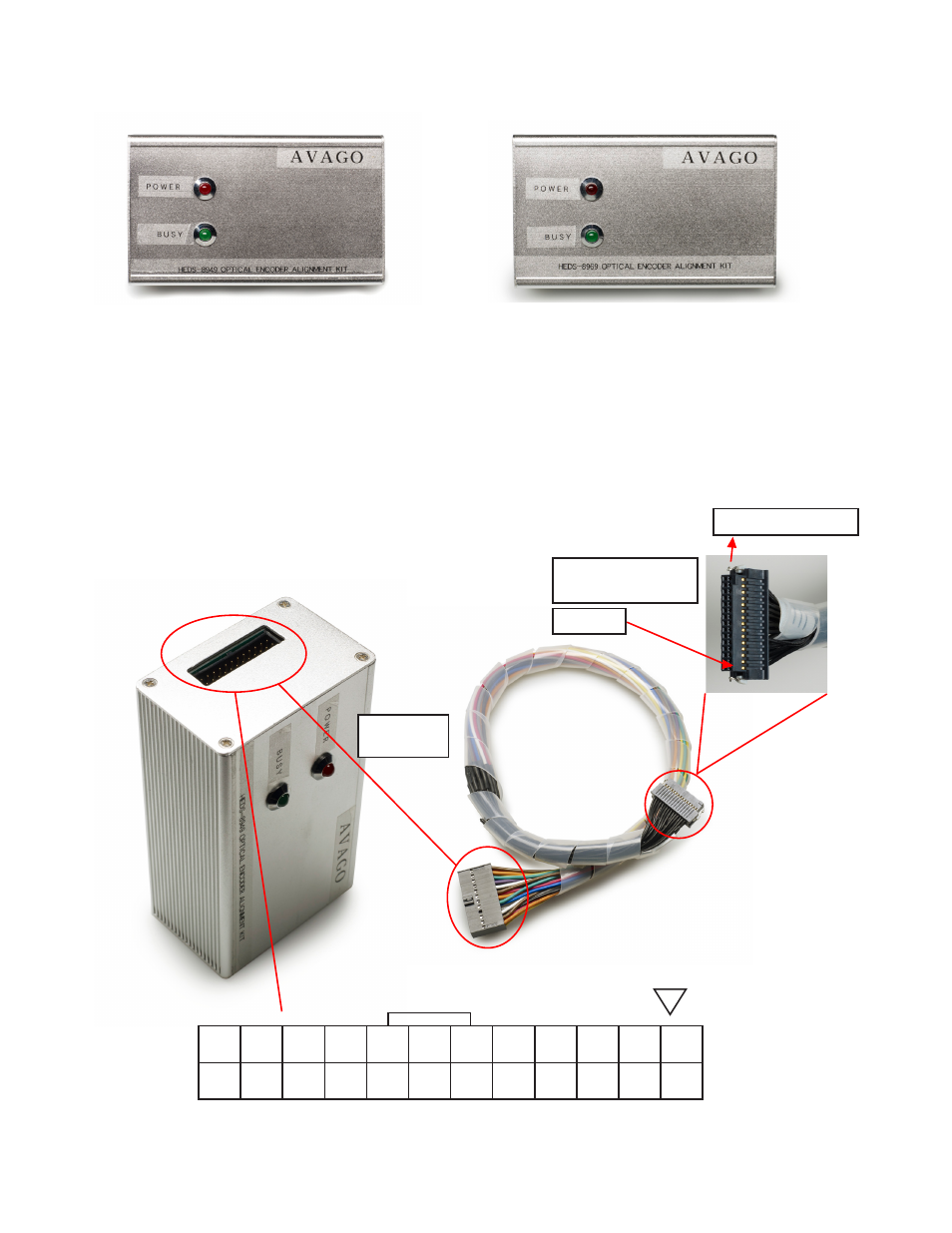
Figure 6. Encoder cable and connectors: 24-way cable for connecting the encoder IC of the target system
Connect the alignment kit to your PC using the provided USB cable. When the alignment module is powered-up the red
LED will illuminate. The green LED will blink when there is communication between the PC and encoder.
The kit’s current consumption is less than 200 mA. The kit includes a 100 mA current limiting circuit for the encoder.
If the current consumption for the alignment kit exceeds 100 mA, the programmer will cut off the supply to the encoder.
On the left side of the programmer is the programming connector, which is a 24-pin (2 x 12) rectangular header.
This connector is used to connect a cable harness to the encoder. Figure 6 shows the encoder cable and connectors.
The programming connector pin names and function are described in Table 1 (shown on next page).
Matching
Connector
Encoder Connector
(To Target System)
Pin 1
23
21
19
17
15
13
11
9
7
5
3
1
24
22
20
18
16
14
12
10
8
6
4
2
Use for AEAT-9000-1GSH0
Figures 4 and 5 show the HEDS-8949/ HEDS-8969 alignment modules.
Figure 5. Alignment module top cover for HEDS-8969
Figure 4. Alignment module top cover for HEDS-8949