Flow meter fc01-lq, 1 calorimetric monitoring procedure – ETA Systems FC01-LQ User Manual
Page 8
Flow Meter FC01-LQ
Flow Meter FC01-LQ
2
Description
2
Description
1.1 Calorimetric monitoring procedure
The calorimetric measuring procedure is based on the physics of heat dissipation.
A body with a temperature higher than its surroundings supplies a medium flowing past that
body with energy in the form of heat. The amount energy supplied is a function of temperature
difference
Δϑ and mass flow.
The thermal measuring method CTD (Constant-Temperature-Difference) is based on following
principle:
The temperature difference
Δϑ between the two sensors is kept constant and the mass flow is
determined by measuring the calorific power.
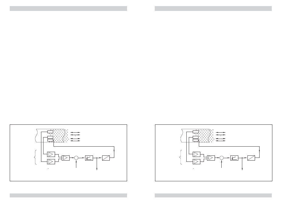
Fig. 1 is a schematic diagram of a CTD method based sensor.
Two temperature-sensitive resistors (sensor elements RS and RM) are immersed in the medium.
Sensor RM assumes the temperature of the medium
ϑ
M
whilst heater resistor RH heats element
RS to temperature
ϑ
S
. As a function of the medium, the temperature differential
Δϑ = ϑ
S
-
ϑ
M
is
preselected as a reference variable by the CTD control and is kept constant. The required heater
current I
H
is a function of mass flow so that the control variable y of the control can be used for
evaluation.
Major benefits of this method are:
●
Fast response, particularly to sudden flow standstill.
●
Medium temperature measurement, providing optimum temperature compensation.
●
Increased safety because the sensor cannot be overheated during flow standstill.
The flow rate is determined by mass flow.
1.1 Calorimetric monitoring procedure
The calorimetric measuring procedure is based on the physics of heat dissipation.
A body with a temperature higher than its surroundings supplies a medium flowing past that
body with energy in the form of heat. The amount energy supplied is a function of temperature
difference
Δϑ and mass flow.
The thermal measuring method CTD (Constant-Temperature-Difference) is based on following
principle:
The temperature difference
Δϑ between the two sensors is kept constant and the mass flow is
determined by measuring the calorific power.
Fig. 1 is a schematic diagram of a CTD method based sensor.
Two temperature-sensitive resistors (sensor elements RS and RM) are immersed in the medium.
Sensor RM assumes the temperature of the medium
ϑ
M
whilst heater resistor RH heats element
RS to temperature
ϑ
S
. As a function of the medium, the temperature differential
Δϑ = ϑ
S
-
ϑ
M
is
preselected as a reference variable by the CTD control and is kept constant. The required heater
current I
H
is a function of mass flow so that the control variable y of the control can be used for
evaluation.
Major benefits of this method are:
●
Fast response, particularly to sudden flow standstill.
●
Medium temperature measurement, providing optimum temperature compensation.
●
Increased safety because the sensor cannot be overheated during flow standstill.
The flow rate is determined by mass flow.
RM
RS
RH
m
K
p
K
p
S
M
K
p
−
+
-x
xd
w
y
K
p
,T
n
U
I
I
H
y
m: mass flow
w: reference variable (
)
x : actual value (
S
-
M
)
xd: system deviation
y : control variable
I
H
: heater current
control loop
medium
ϑ
ϑ
ϑ ϑ
ϑ
Δ
fig. 1
RM
RS
RH
m
K
p
K
p
S
M
K
p
−
+
-x
xd
w
y
K
p
,T
n
U
I
I
H
y
m: mass flow
w: reference variable (
)
x : actual value (
S
-
M
)
xd: system deviation
y : control variable
I
H
: heater current
control loop
medium
ϑ
ϑ
ϑ ϑ
ϑ
Δ
fig. 1