Flow meter fc01-lq – ETA Systems FC01-LQ User Manual
Page 14
Flow Meter FC01-LQ
Flow Meter FC01-LQ
8
Installation
8
Installation
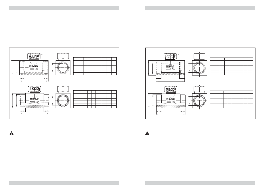
2.2.1.1 Sensoradapter TP-..
The sensor adapter TP-.. is available in 6 pipe diameters from 1/2" to 2".
Sensor adapter is available as screw-in (fig. 4 top) or welding type (fig. 4 bottom).
Material of the area exposed to medium:
- brass or
- stainless steel 1.4571/AISI 316 Ti
2.2.1.1 Sensor adapter TP-..
The sensor adapter TP-.. is available in 6 pipe diameters from 1/2" to 2".
Sensor adapter is available as screw-in (fig. 4 top) or welding type (fig. 4 bottom).
Material of the area exposed to medium:
- brass or
- stainless steel 1.4571/AISI 316 Ti
G
t
L
t
SW
ød
ød
27
32
40
50
55
70
SW
50
64
78
94
110
138
11
12
14
15
15
19
t
ød
16
20
25
32
40
50
DN
Type
TP-01 …
TP-02 …
TP-03 …
TP-04 …
TP-05 …
TP-06 …
15
20
25
32
40
50
G
1/2"
3/4"
1"
1 1/4"
11/2"
2"
L
t
t
L
SW
øD
DN
15
20
25
32
40
50
27
32
40
50
55
70
SW
50
70
80
100
110
140
15
15
15
15
15
15
t
ød
16
20
25
32
40
50
Type
TP-01M1-SA
TP-02M1-SA
TP-03M1-SA
TP-04M1-SA
TP-05M1-SA
TP-06M1-SA
L
øD
21.3
26.9
33.7
42.4
48.3
60.3
retention pin
fig. 4
2.2.1.2 Mounting instructions (monitoring head CSP-.. with sensor adapter TP-.. )
Caution!
The monitoring head should only be installed or removed when the pipes are unpressurised.
To ensure the safety label is clearly visible, it should be affixed on to or close to the measuring point.
● Insert the monitoring head with the O ring into the sensor adapter and tighten the union
nut (observe correct retention).
The retention pin ensures correct alignment of the monitoring head after the union nut has
been tightened.
Correct immersion depth of the monitoring head is ensured by the stop provided.
Sealing of the monitoring head in the sensor adapter is by means of the O ring provided (fig. 3).
● Screw the sensor adapter into the pipe, using hemp or teflon tape for sealing.
G
t
L
t
SW
ød
ød
27
32
40
50
55
70
SW
50
64
78
94
110
138
11
12
14
15
15
19
t
ød
16
20
25
32
40
50
DN
Type
TP-01 …
TP-02 …
TP-03 …
TP-04 …
TP-05 …
TP-06 …
15
20
25
32
40
50
G
1/2"
3/4"
1"
1 1/4"
11/2"
2"
L
t
t
L
SW
øD
DN
15
20
25
32
40
50
27
32
40
50
55
70
SW
50
70
80
100
110
140
15
15
15
15
15
15
t
ød
16
20
25
32
40
50
Type
TP-01M1-SA
TP-02M1-SA
TP-03M1-SA
TP-04M1-SA
TP-05M1-SA
TP-06M1-SA
L
øD
21.3
26.9
33.7
42.4
48.3
60.3
retention pin
fig. 4
2.2.1.2 Mounting instructions (monitoring head CSP-.. with sensor adapter TP-.. )
Caution!
The monitoring head should only be installed or removed when the pipes are unpressurised.
To ensure the safety label is clearly visible, it should be affixed on to or close to the measuring point.
● Insert the monitoring head with the O ring into the sensor adapter and tighten the union
nut (observe correct retention).
The retention pin ensures correct alignment of the monitoring head after the union nut has
been tightened.
Correct immersion depth of the monitoring head is ensured by the stop provided.
Sealing of the monitoring head in the sensor adapter is by means of the O ring provided (fig. 3).
● Screw the sensor adapter into the pipe, using hemp or teflon tape for sealing.